Optical coherent receiver, apparatus for and method of monitoring performance thereof

a technology of optical coherent receiver and optical layer, applied in the field of optical communication, can solve the problems of difficult structure of optical coherent receiver, inability to directly and precisely reflect the physical layer working performance of the receiver, and the inability to use statistics about the bit error rate that take a considerable amount of time, so as to quickly and precisely reflect the change in the performance of the receiver

Active Publication Date: 2010-04-15
FUJITSU LTD
View PDF1 Cites 17 Cited by
  • Summary
  • Abstract
  • Description
  • Claims
  • Application Information

AI Technical Summary

Benefits of technology

[0022]The apparatus and method according to the present invention can quickly and precisely reflect the change in performance of the receiver. Monitoring results provided by the claimed apparatus and method can be applied to positioning of receiver failures, adjustment of receiver control parameters and estimation of channel characteristics, etc.

Problems solved by technology

The structure of an optical coherent receiver is also complicated relative to the traditional incoherent or self-coherent receiver.
Accordingly, the bit error rate obtained by such statistics is further subjected to influences of non-physical layer factors (such as the multiplexing mode of the receiver and the frame structure of the transmission data, etc.), so that the bit error rate cannot directly and exactly reflect the physical layer working performance of the receiver.
Moreover, statistics about the bit error rate usually takes a considerable lot of time, fifteen minutes or an hour for instance, and such lengthy period of time is obviously to the detriment of failure positioning and removal.

Method used


Image

  • Optical coherent receiver, apparatus for and method of monitoring performance thereof
  • Optical coherent receiver, apparatus for and method of monitoring performance thereof
  • Optical coherent receiver, apparatus for and method of monitoring performance thereof

Examples


Embodiment Construction

[0035]The apparatus for and method of monitoring performance of an optical coherent receiver according to the present invention are described in greater detail below with reference to the accompanying drawings.

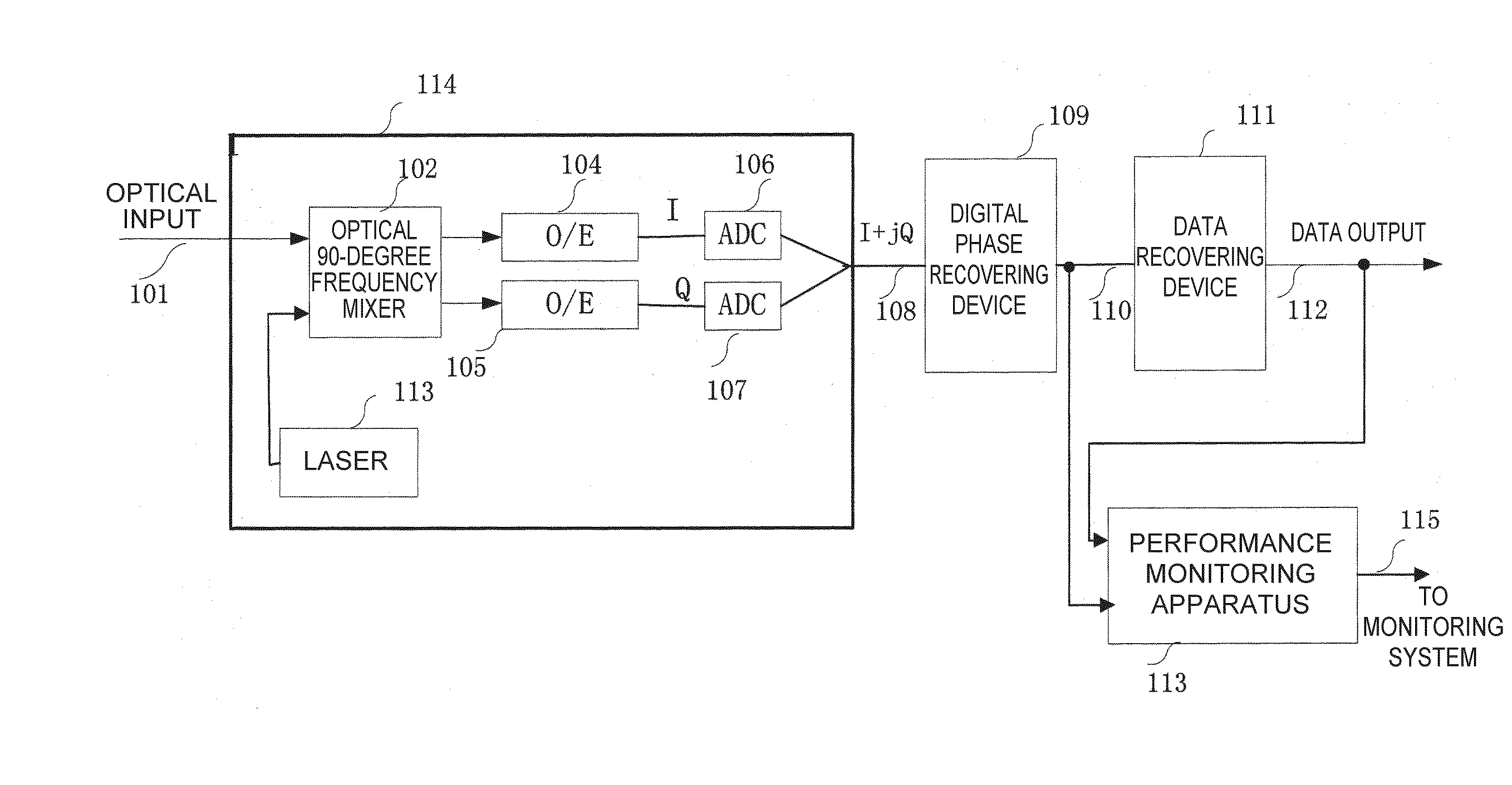
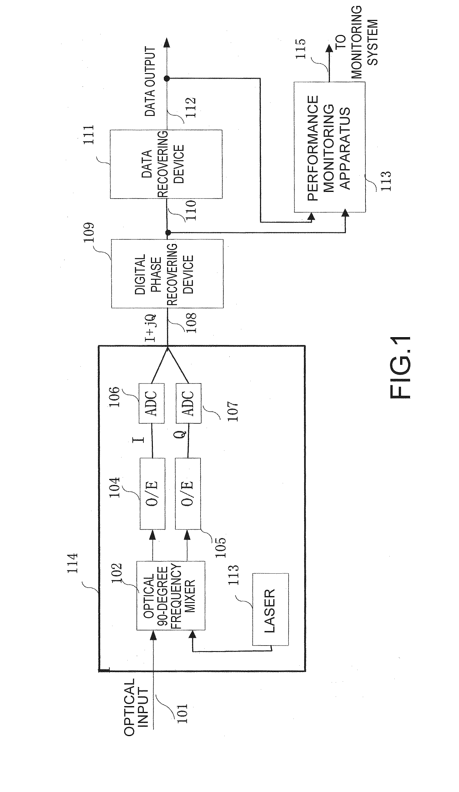
[0036]FIG. 1 illustrates an optical coherent receiver having the apparatus for monitoring performance according to the present invention. The optical 90-degree frequency mixer 102, the optoelectric (O / E) converters 104 and 105, the analog-to-digital converters (ADC) 106 and 107, and the laser 103 in FIG. 1 constitute the front end 114 of an optical coherent receiver. Function of this section is to convert the received optical signal 101 into a baseband electric signal 108. The baseband electric signal 108 can be expressed as I+jQ. In general circumstances, the argument of the baseband electric signal 108 includes not only the data information φd, but also the phase offset φ0 between carrier and local oscillation as well as the influence φn of the noise on the phase. Function o...


PUM


Abstract

The present invention relates to an optical coherent receiver and an apparatus for and a method of monitoring performance thereof. The apparatus for monitoring performance of the optical coherent receiver makes use of a first signal and a second signal from the optical coherent receiver to monitor performance of the optical coherent receiver, and comprises a first subtracter, for subtracting the second signal from the first signal to obtain a first subtraction result; a squarer, for obtaining a square of the first subtraction result; a delayer, for delaying the first subtraction result; a multiplier, for multiplying the first subtraction result with the delayed first subtraction result; and a second subtracter, for subtracting the result of the multiplier from the result of the squarer.

Description

FIELD[0001]The present invention relates to optical communications, and more particularly to an optical coherent receiver.BACKGROUND[0002]With the gradual enhancement of the requirements for capacity and flexibility of the optical communications system, coherent optical communications technology becomes more and more important. In comparison with incoherent technologies (such as on-off key, OOK) or self-coherent technologies (such as differential quadrature phase shift keying DQPSK), the coherent technology has the following advantages: a gain of 3 dB optical signal-to-noise ratio (OSNR), the possibility to employ more efficient modulation technologies (such as quadrature modulation, QAM) to enhance transmission capacity, the convenient use of electric equalization technology to respond to changes in channels, and to reduce production costs, etc.[0003]The structure of an optical coherent receiver is also complicated relative to the traditional incoherent or self-coherent receiver. F...

Claims


Application Information

Patent Timeline
Patent Type & Authority Applications(United States)
IPC IPC(8): H04B10/08H04B10/07G01J9/00H04B10/079H04B10/40H04B10/50H04B10/60H04B10/61
CPCH04B10/0795H04B10/611H04B10/60H04B10/65
Inventor LI, LEITAO, ZHENNINGNAKASHIMA, HISAO
Owner FUJITSU LTD
Why Eureka
Try Eureka