
Method and Apparatus for a Rules-Based Utilization of a Minimum-Slit-Head Configuration Plunger Slitter

a configuration plunger and slitter technology, applied in the field of rules-based utilization of slitter configuration plungers, can solve the problems of increasing the cost and complexity of slitter/scorer, and being unable to achieve, so as to reduce the support structure of the slitter scorer, improve the reliability of order change, and reduce the length of waste material.

Inactive Publication Date: 2010-04-15
BARRY WEHMILLER PAPERSYST INC
View PDF11 Cites 5 Cited by
  • Summary
  • Abstract
  • Description
  • Claims
  • Application Information

AI Technical Summary

Benefits of technology

[0011]A further objective of the invention is to minimize the length of waste material generated during the order change by accomplishing the change over from one job to the next as quickly as possible.
[0012]Another objective of a particularly advantageous embodiment of this invention is to provide a trim slit change-over method that will significantly improve order change-over reliability.
[0013]Yet another objective of the invention is to reduce the head support structure of the slitter scorer that will minimize the overall cost of the slitter / scorer.
[0014]It is also an objective of the invention to provide a slitting method that will require a small number of head positioning robots so as to reduce the overall cost and complexity of the slitter and to achieve a high reliability.SUMMARY OF THE INVENTION

Problems solved by technology

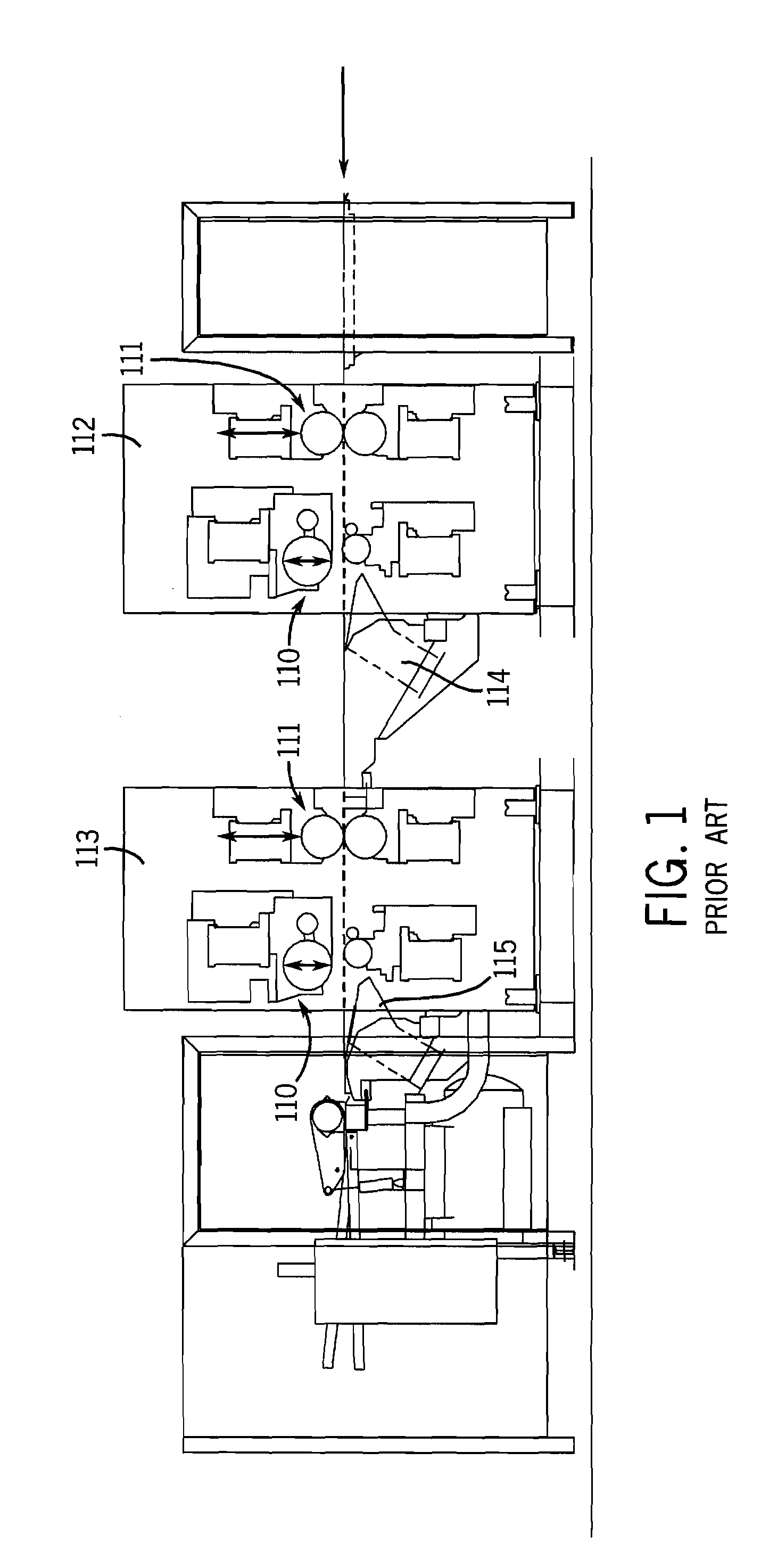
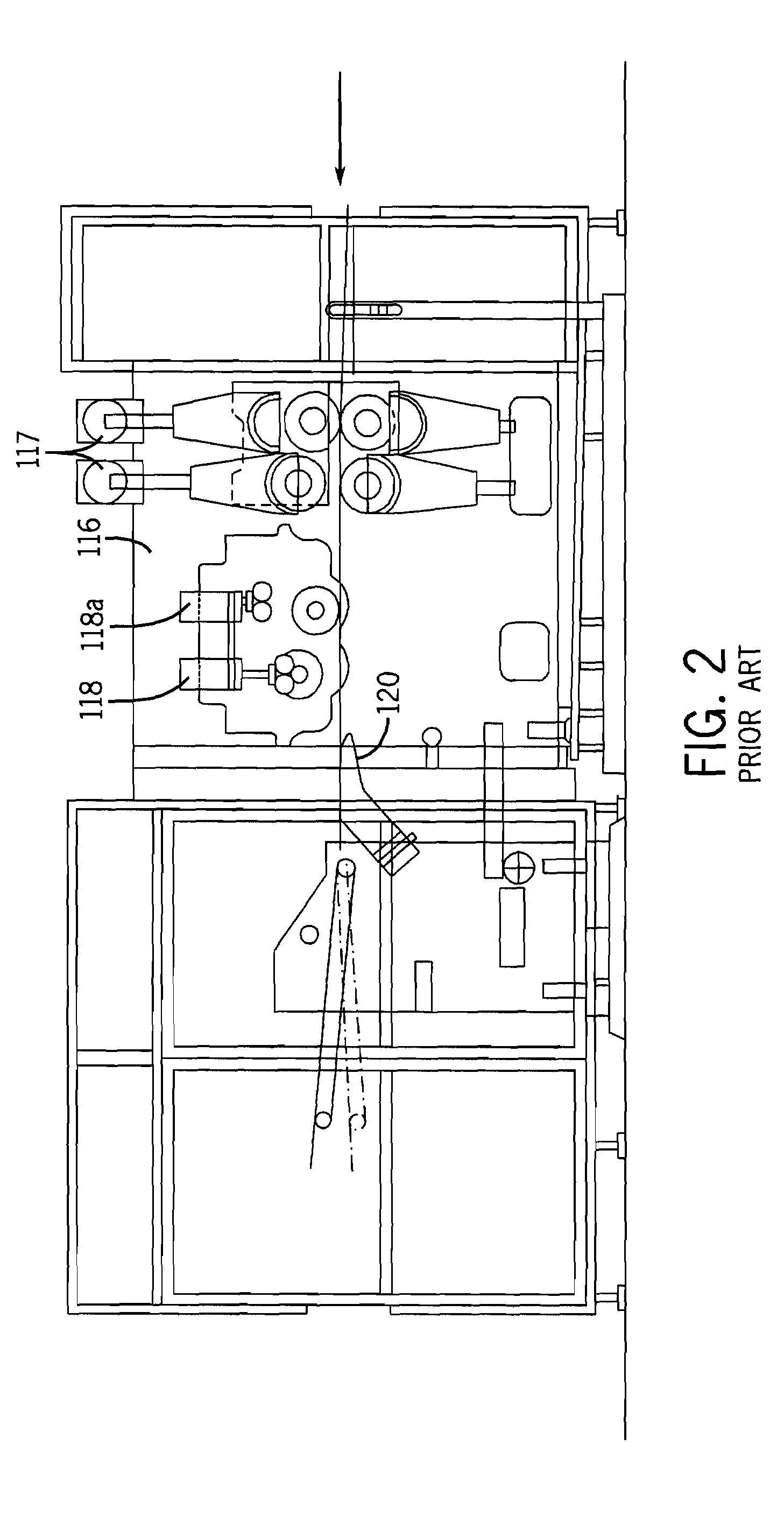
A disadvantage of the two station plunge slitter concepts is that there is a duplication of slit and score heads that increases the cost and complexity of the slitter / scorer.
In practice, this is not possible because of physical space occupied by the slit heads and the sometimes small difference between old and new order slit positions.

Method used


Image

  • Method and Apparatus for a Rules-Based Utilization of a Minimum-Slit-Head Configuration Plunger Slitter
  • Method and Apparatus for a Rules-Based Utilization of a Minimum-Slit-Head Configuration Plunger Slitter
  • Method and Apparatus for a Rules-Based Utilization of a Minimum-Slit-Head Configuration Plunger Slitter

Examples


Embodiment Construction

[0024]Prior art slitter / scorers have used two in-line series of rotary scoring tools and two in-line series of rotary slitting tools to make it possible to process one job on one series of slitting and scoring tools while the other series of slitting and scoring tools is positioned by robots for the processing of the next job. For a six-out slitter / scorer, there are a minimum of five internal slit heads required on one job. The prior art slitter / scorers utilize five internal slit heads on each slitter series.

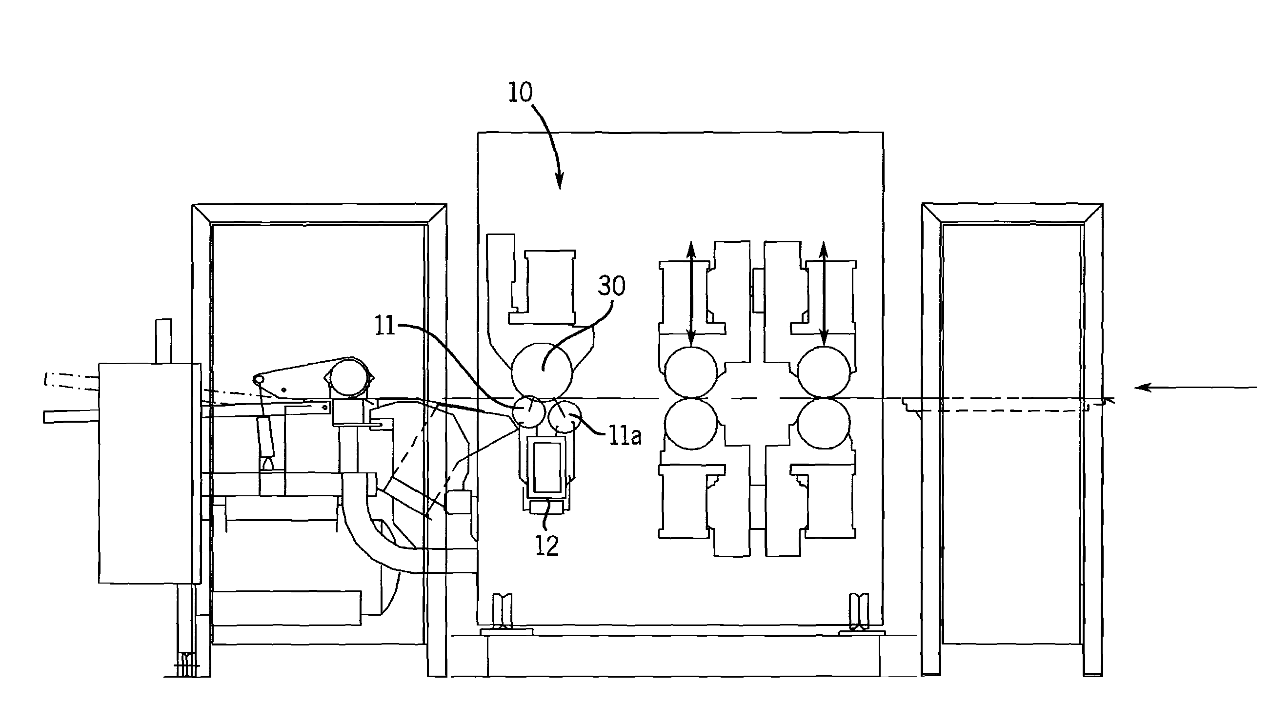
[0025]FIG. 5 shows one embodiment of the single axis slitter / scorer 10 of the present invention. The slitter of the present invention, as also shown in FIG. 6, has three rotary plunge-style slit heads 11, 11a mounted on each side of a single tool support structure 12 for the preferred embodiment, or four fewer internal slit tools than the FIG. 4 prior art design. The slit heads or tools 11, 11a are operable to provide the slit lines defining the output webs or “outs” and will he...


PUM

PropertyMeasurementUnit
Widthaaaaaaaaaa

Abstract

A method and apparatus for performing an order change in a corrugator uses a minimum slit head configuration with all slit heads carried on two sides of a single tool support structure. A single robot is operable on the support structure to independently reset the positions of slit heads during a running order to prepare for subsequent order change in a most efficient manner, utilizing order scheduling that eliminates order changes that cannot be formed with the minimum slit head configuration.

Description

CROSS REFERENCE TO RELATED APPLICATIONS[0001]This application relates to and claims priority from U.S. Provisional Patent Application Ser. No. 61 / 105,456, filed Oct. 15, 2008.BACKGROUND OF THE INVENTION[0002]The present invention pertains to a system for facilitating an order change in the dry end conversion of a corrugated paperboard web. In particular, the invention relates to a method and apparatus for accomplishing an order change using a minimum slit head configuration slitter.[0003]In a corrugator dry end, where a corrugated paperboard web is longitudinally scored and slit into multiple parallel output webs (or “outs”), the outs are directed through one or more downstream cut-off knives which cut the output webs into selected sheet lengths. When two cut-off knives are used, they are vertically separated and each is capable of cutting the full corrugator width web. A web selector positioned downstream of the slitter / scorer, divides the outs into two groups, one of which is dire...

Claims


Application Information

Patent Timeline
IPC IPC(8): B26D7/26B31F7/00B31B50/18
CPCB26D1/225B26D1/245B26D5/00B26D7/1863B26D5/02B26D9/00B26D11/00B26D2007/0068B31F1/2822B26D7/2635Y10T83/7826
Inventor CUMMINGS, JAMES A.KONDRATUK, JOHN J.
Owner BARRY WEHMILLER PAPERSYST INC
Learn More