Variable speed self-expanding stent delivery system and luer locking connector

a self-expanding, stent technology, applied in the field of stent delivery systems, can solve the problems of affecting the accuracy of stent placement, affecting the safety of patients, so as to minimize the imposition of unwanted stresses on the bodily tissue, reduce the effect of fingertip sensitivity and accurate and precise control

Inactive Publication Date: 2010-04-15
ANGIOMED GMBH & CO MEDIZINTECHNIK KG
View PDF102 Cites 134 Cited by
  • Summary
  • Abstract
  • Description
  • Claims
  • Application Information

AI Technical Summary

Benefits of technology

[0022]In short, what the present inventor has found is that a release device which embodies both a ratchet means and a full stroke actuator is one which allows a range of individual medical practitioners, all of whom have their own preferred techniques for precise stent deployment, to practice their skilled techniques in the way that suits them best, to lay down an initial part of the length of a stent in a precise location in a bodily lumen, and then to complete the deployment of the length of the stent in a way which is so accurately and precisely controlled that the practitioner can satisfactorily avoid imposing unacceptable axial stresses on the tissue being stented.
[0023]In presently preferred embodiment, the device of the invention is realized in a device which offers the medical practitioner a trigger for successive pumping to withdraw the stent-surrounding sheath proximally stepwise, together with a slider which allows the operator to withdraw the sleeve in one stroke. Thus, the trigger provides the ratchet means of the invention and the slider provides the full stroke actuator of the invention. The inventor envisages that it will be convenient for many practitioners to utilize the trigger during the first phase of stent deployment and then, when satisfied that the stent is placed within the bodily lumen as desired, switch from the trigger to the slider in order to deploy the remaining length of the stent with as much fingertip sensitivity as possible, thereby to minimize the imposition of unwanted stresses on the bodily tissue.

Problems solved by technology

During sterilization and packaging, there is always the risk that the co-axial components of the assembly might move so that the outer sheath may be displaced with respect to the inner catheter.
There continue to be difficulties for medical practitioners in placing the stent exactly as required.
At this point, the stent is bound to both the delivery system and the bodily lumen wall, so that any axial movement of the delivery system relative to the bodily lumen is liable to cause injury to the lumen wall.

Method used


Image

  • Variable speed self-expanding stent delivery system and luer locking connector
  • Variable speed self-expanding stent delivery system and luer locking connector
  • Variable speed self-expanding stent delivery system and luer locking connector

Examples


Embodiment Construction

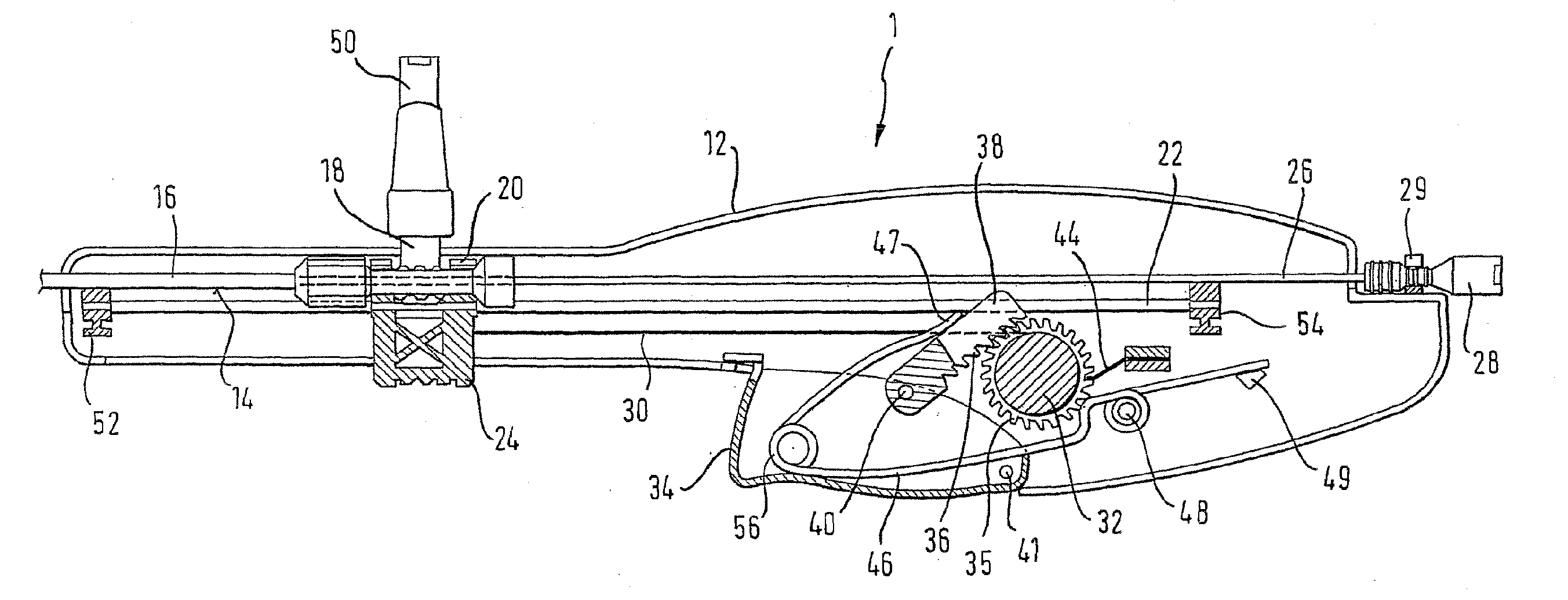
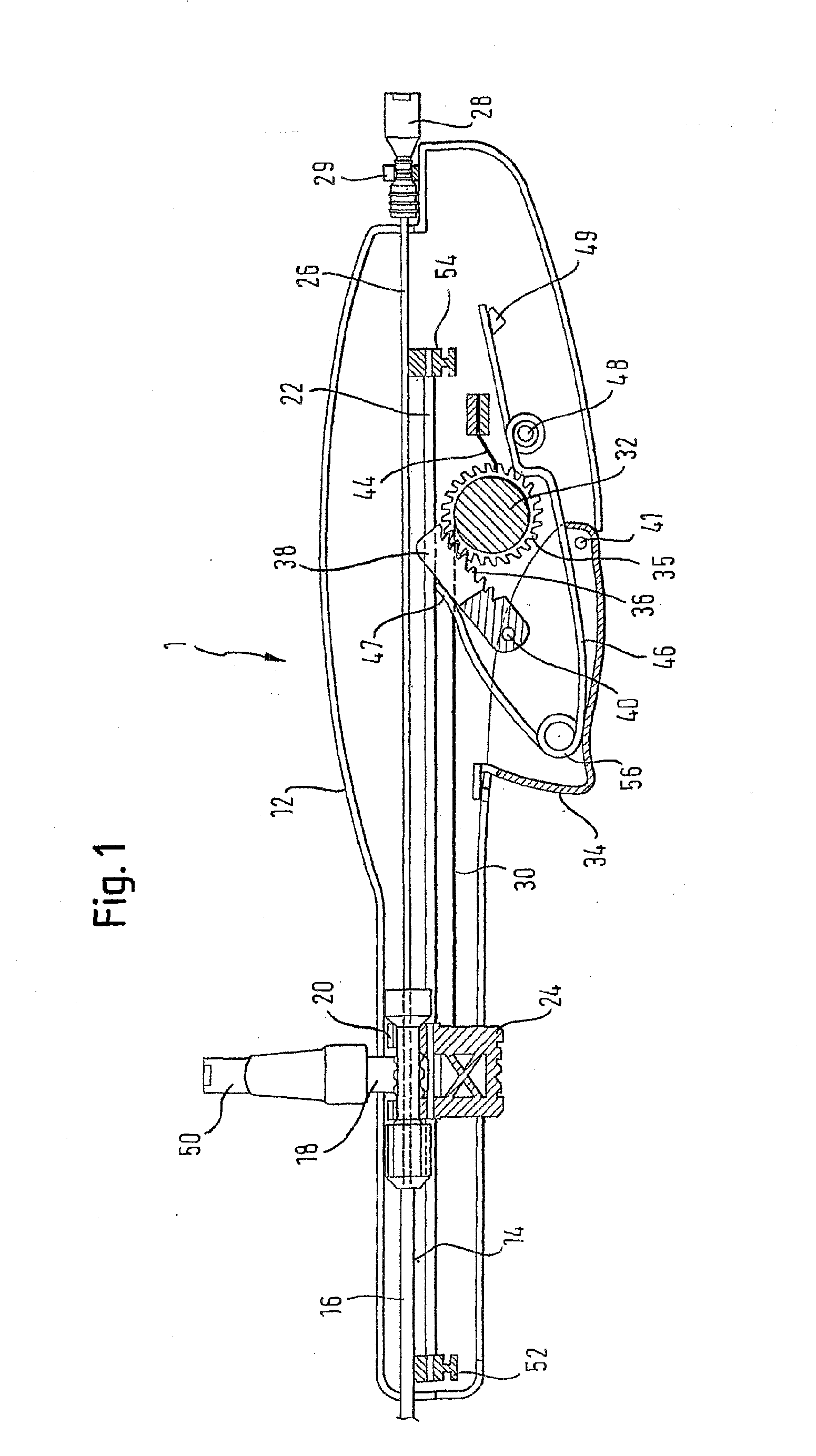
[0037]The drawings are of a preferred embodiment of the invention and FIG. 1 shows one half 12 of a molded housing of which the other half lies above the plane of the drawing.

[0038]The two housing halves define, in an assembled state, a track 14 in which can be laid the proximal end of a co-axial stent delivery device having an outer tube 6. Track 14 is formed by mating axial recesses in the two housing halves, resulting in a semi-circular channel open to the upper end in FIG. 1 of the housing.

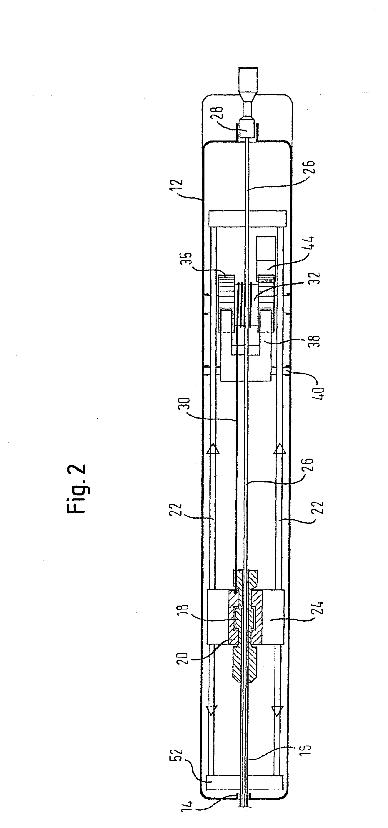
[0039]The proximal end of the outer tube 16 carries a hub 18 which is received within a yoke 20 of a slider 24 which itself runs on a pair of rails 22. The rails 22 are not integral molded parts of the housing and are held in place by advancing a first one of the rails through a hole (not show in FIG. 1) and through fixing part 52 and feed hole in slider 24 at the distal end of the housing and into blind hole at fixing point 54 distal from the proximal end of the housing. The distal end of the...


PUM


Abstract

A stent delivery system that includes an inner member and an outer retractable sheath is operated by a handle that permits retraction of the sheath at more than one speed. The sheath may be retracted in small, incremental steps or in a single, more rapid stroke. Means are provided for releasably locking the inner member and outer sheath in a fixed position as well as to facilitate admission of liquid into the device.

Description

FIELD OF THE INVENTION[0001]This invention relates to stent delivery systems.BACKGROUND[0002]The deployment of stents at a stenting site within a human or animal body requires careful handling of the stent delivery system to be used for deploying the stent. Exact positioning of the stent at the site of the stenosis prior to and during deployment is essential. The accuracy with which the stent can be deployed with respect to the occlusion inside the body lumen, as well as the skills of the surgeon in controlling the stent delivery system, will having an impact on the outcome of the operation.[0003]Normally, a guidewire is used, to advance a stent delivery system containing the stent to be deployed into the body to the site of the stenosis. Once the distal end of the delivery system has reached the stenting site and the stent to be released is correctly located, the stent is released. To deploy a self-expanding stent it is known to gradually withdraw an outer sheath (otherwise called ...

Claims


Application Information

Patent Timeline
Patent Type & Authority Applications(United States)
IPC IPC(8): A61F2/84A61F2/95A61M39/10
CPCA61F2/95A61F2/966A61M39/1011A61F2002/9517A61F2/9517
Inventor DORN, JURGENVOGEL, MICHAEL
Owner ANGIOMED GMBH & CO MEDIZINTECHNIK KG
Why Eureka
Try Eureka