Solar cell including backside reflection layer composed of high-k dielectrics

a solar cell and backside reflection technology, applied in the field of solar cells, can solve the problems of increasing the limit reducing and not having excellent reflectivity of conventional reflection layer, so as to achieve excellent optical trapping of solar rays and reduce the recombination of backside carriers

Inactive Publication Date: 2010-04-22
LG ELECTRONICS INC
View PDF14 Cites 11 Cited by
  • Summary
  • Abstract
  • Description
  • Claims
  • Application Information

AI Technical Summary

Benefits of technology

[0006]The present invention is designed to solve the problems of the prior art, and therefore it is an object of the present invention to provide a solar cell capable of decreasing recombination of a backside of a carrier with ensuring excellent optical trapping for solar rays.

Problems solved by technology

However, a conventional reflection layer does not have excellent reflectivity and sufficient prevention of recombination of carriers.
In addition, due to bad thermal stability, the conventional reflection layer has a limit in increasing a temperature of a thermal treatment process used for forming a rear electrode.

Method used


Image

  • Solar cell including backside reflection layer composed of high-k dielectrics
  • Solar cell including backside reflection layer composed of high-k dielectrics

Examples


Embodiment Construction

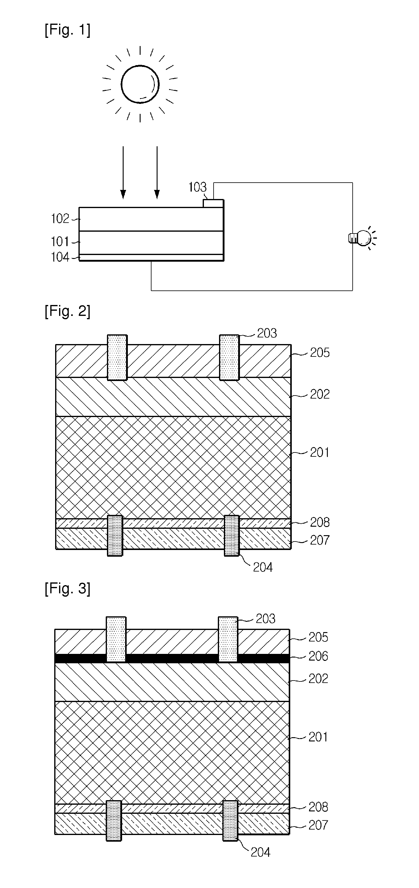
[0013]Hereinafter, preferred embodiments of the present invention will be described in detail with reference to the accompanying drawings.

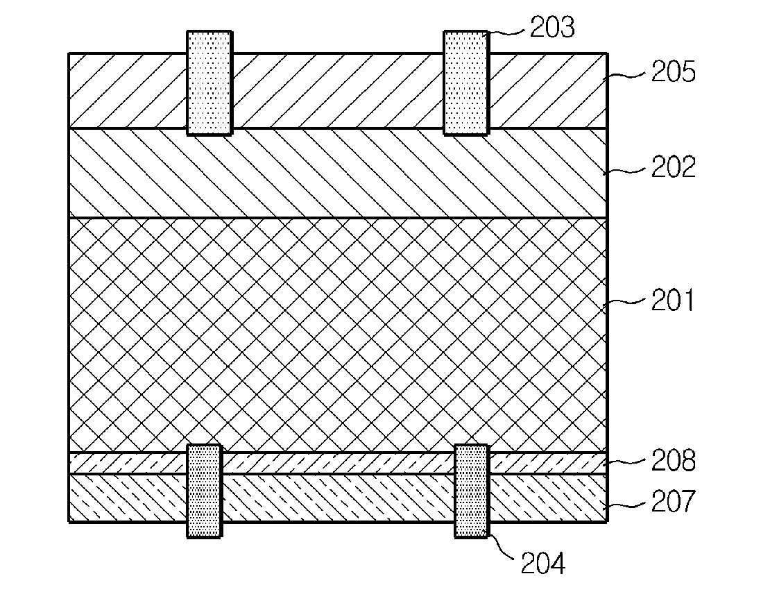
[0014]FIG. 2 is a schematic view showing a solar cell according to a first embodiment of the present invention. As shown in FIG. 2, the solar cell according to the present invention includes a p-n junction structure, an anti-reflection layer 205, a front electrode 203, a rear electrode 204, a reflection film 207 and a backside passivation layer 208.

[0015]The p-n junction structure includes a first conductive silicon layer 201, a second conductive silicon layer 202 having a conduction opposite to the first conductive silicon layer 201, and a p-n junction formed at an interface between the first and second conductive silicon layers 201, 202. The p-n junction structure receives light to generate electric current by means of a photovoltaic effect. The p-n junction structure is made by forming, on the first conductive silicon layer, the second conducti...


PUM


Abstract

A solar cell includes a backside reflection layer containing a high-k dielectrics. The backside reflection layer includes a reflection film containing HfO2 or ZrO2 and a backside passivation layer containing of HfSixOy, ZrSixOy or SiO2, which are formed on a rear side of a substrate onto which solar rays are input. Thus, the solar cell exhibits excellent optical trapping for solar rays and low recombination rate of carriers on the rear side. Also, since the reflection film and the backside passivation layer have excellent thermal stability, it is possible to form electrodes by applying various processes such as thermal treatment.

Description

TECHNICAL FIELD[0001]The present invention relates to a solar cell, and more particularly to a solar cell capable of decreasing recombination of a backside of a carrier with ensuring excellent optical trapping for solar rays.BACKGROUND ART[0002]Recently, as exhaustion of existing energy resources such as petroleum and coal is estimated, interests on alternative energies for substituting them are more increased. Among the alternative energies, a solar cell is particularly spotlighted since its energy resource is sufficient and it does not cause any environmental pollution. A solar cell is classified into a solar heat cell that generates a vapor required for rotating a turbine using a solar heat, and a solar light cell that converts photons into electric energy using the properties of a semiconductor. Generally, a solar cell calls the solar light cell (hereinafter, the term ‘solar cell’ is used).[0003]Referring to FIG. 1 showing a basic structure of a solar cell, the solar cell has a ...

Claims


Application Information

Patent Timeline
Patent Type & Authority Applications(United States)
IPC IPC(8): H01L31/028
CPCY02E10/52H01L31/02167H01L31/02168H01L31/1868H01L31/056H01L31/02327Y02E10/545Y02E10/546Y02E10/547H01L31/0216Y02P70/50H01L31/04H01L31/06H01L31/054
Inventor PARK, HYUNJUNG
Owner LG ELECTRONICS INC
Why Eureka
Try Eureka