Method of Forming a Hardened Skin on a Surface of a Molded Article

a molding method and hardening technology, applied in the field of flow molding, can solve the problems of not being easily washable, not sufficiently durable to withstand abrasion, and many foamed plastic parts made in accordance with these methods

Active Publication Date: 2010-04-22
NOVATION IQ LLC
View PDF18 Cites 8 Cited by
  • Summary
  • Abstract
  • Description
  • Claims
  • Application Information

AI Technical Summary

Benefits of technology

[0012]The present invention is directed to a method of forming a hardened skin on one or more surfaces of a molded article. In accordance with this method, a formable material is mixed with a blowing agent to form a foam material. The foam material is then placed in a flow molding apparatus whereby an alternating dielectric field is applied across the foam material to form the molded article. Typically, most of the foam material exceeds the decomposition temperature of the blowing agent and is fully blown at the end of the molding cycle. However, one or more surfaces of the foam material remain under the decomposition temperature of the blowing agent and are not blown so as to form one or more thicknesses of hardened skin on the molded article. The method of the present invention enables the fabrication of molded articles with hardened skins that are sufficiently durable to withstand the abrasion that occurs during normal use of the articles, are easily washable, may be texturized as desired, and / or include a non-skid surface as required for particular applications.

Problems solved by technology

Many of the foamed plastic parts made in accordance with these methods, however, are not sufficiently durable to withstand the abrasion that occurs during normal use of the parts, are not easily washable, cannot be texturized as desired, and / or do not include a non-skid surface as required for particular applications.

Method used


Image

  • Method of Forming a Hardened Skin on a Surface of a Molded Article
  • Method of Forming a Hardened Skin on a Surface of a Molded Article
  • Method of Forming a Hardened Skin on a Surface of a Molded Article

Examples


first exemplary embodiment

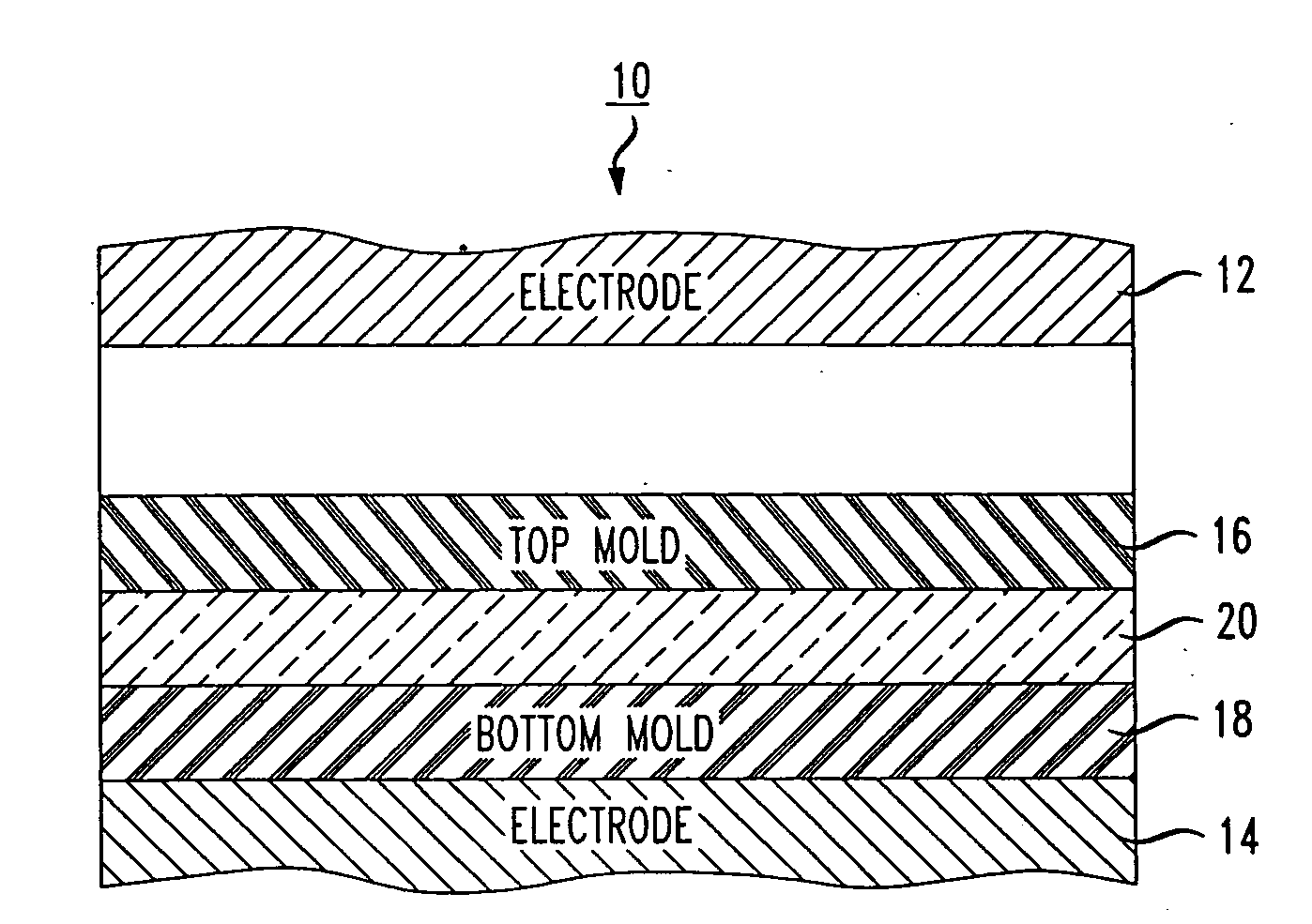
[0027]Referring to FIG. 1, a first exemplary embodiment of the method of the present invention will now be described with reference to the diagram of a flow molding apparatus designated generally as numeral 10. Flow molding apparatus 10 includes a top electrode 12 and a bottom electrode 14, both of which are connected to an electromagnetic energy source (not shown) operable to generate an alternating electric field between the electrodes. The alternating electric field may be generated at frequencies ranging from 1 MHz to 500 MHz, is preferably generated at frequencies ranging from 10 MHz to 100 MHz, and is most preferably generated at either 26 MHz or 40 MHz. Also included within apparatus 10 are a top mold 16 and a bottom mold 18 that together define a molding cavity therebetween.

[0028]In the illustrated example, a foam material 20 is placed within the molding cavity such that a top surface of foam material 20 is in contact with top mold 16 and a bottom surface of foam material 20...

example 1

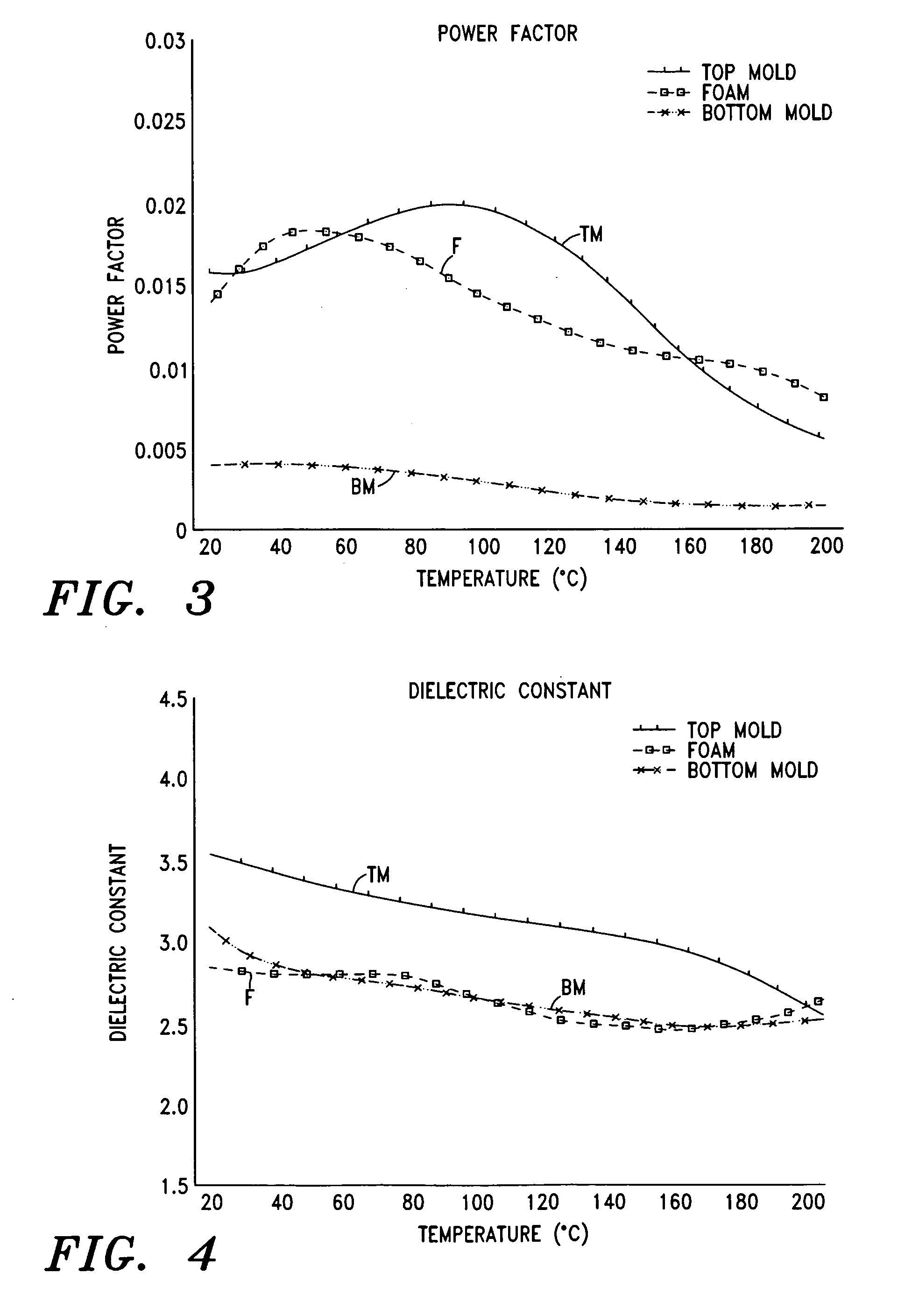
[0134]Assume for purposes of this example that top mold 16 and bottom mold 18 of flow molding apparatus 10 are each formed from silicone rubber V-1008 (manufactured by Rhodia Inc.) and foam material 20 comprises an EVA foam blend. Table 1 is provided below to show various factors for each of these layers of material, namely, the desired temperature (T) at the end of the molding cycle, thickness (d), power factor (pf), relative dielectric constant (∈), specific heat (h), and specific gravity (ρ). These factors will be used hereinbelow to perform various calculations in accordance with the method of the present invention.

TABLE 1FoamTop MoldMaterialBottom Mold(layer 1)(layer 2)(layer 3)Desired200200Temperature (T)(degrees Celsius)Thickness (d).125.375.125(inches)Power Factor (pf).0137.0033Relative3.072.672.67DielectricConstant (ε)Specific Heat (h)1.2331.5661.233Specific Gravity1.161.0411.16(ρ)

[0135]As can be seen from Table 1, the desired temperature of foam material 20 at the end of t...

example 2

[0155]Assume for purposes of this example that bottom mold 18 is formed from silicone rubber V-1075 (manufactured by Rhodia Inc.), which contains iron oxide and thus has a higher thermal conductivity than the silicone rubber V-1008 used in Example 1. Specifically, the thermal conductivity of silicone rubber V-1075 is 0.0241. All of the calculations and values of Example 1 remain unchanged, with the exception of the following analysis.

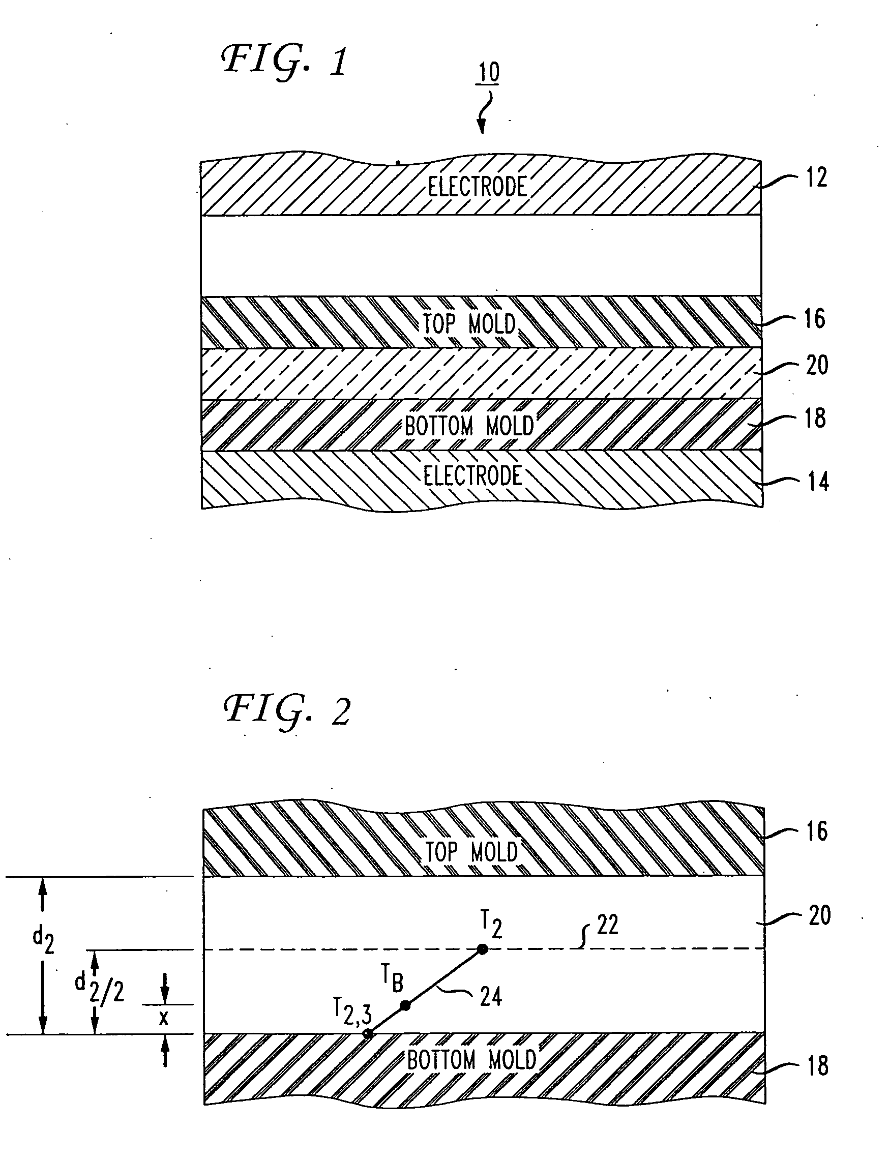
[0156]The temperature at the interface between foam material 20 and bottom mold 18 may be calculated from equation (19) using the temperature (7′3) of bottom mold 18 derived in Example 1 above and the value for the temperature (T2) of foam material 20 shown in Table 1 (assuming that the thermal conductivity of foam material 20 is still 0.00638 while the thermal conductivity of bottom mold 18 is now 0.0241):

T2,3=(.00638×200)+(.0241×55.48).00638+.0241=85.73°C.

[0157]Thus, the temperature at the interface between foam material 20 and bottom mold 18 is now 8...


PUM

PropertyMeasurementUnit
frequenciesaaaaaaaaaa

Abstract

A method of forming a hardened skin on one or more surfaces of a molded article. In an exemplary method, a formable material is mixed with a blowing agent to form a foam material. The foam material is placed in a flow molding apparatus such that a first surface of the foam material is in contact with a first mold section and a second surface of the foam material is in contact with a second mold section. In operation, an alternating dielectric field is applied across the foam material to form the molded article. At the end of the molding cycle, the first and/or second surfaces of the foam material remain under the decomposition temperature of the blowing agent and are not blown so as to form one or more thicknesses of hardened skin on the molded article.

Description

CROSS-REFERENCE TO RELATED APPLICATIONS[0001]This application is a continuation-in-part of, and claims priority to, U.S. patent application Ser. No. 10 / 890,906, filed on Jul. 14, 2004, which is incorporated herein by reference in its entirety.STATEMENT REGARDING FEDERALLY SPONSORED RESEARCH OR DEVELOPMENT[0002]Not applicable.BACKGROUND OF THE INVENTION[0003]1. Field of the Invention[0004]The present invention is generally directed to the field of flow molding, and is more specifically directed to a unique flow molding process for forming a hardened skin on one or more surfaces of a molded article.[0005]2. Description of Related Art[0006]Various flow molding apparatuses are known in the art that employ dielectric heating to mold a plastic part from a formable plastic material. In all of these apparatuses, the plastic material is placed between two electrodes such that the material effectively becomes the dielectric of a capacitor. An alternating electric field generated between the e...

Claims


Application Information

Patent Timeline
Patent Type & Authority Applications(United States)
IPC IPC(8): B29C67/20
CPCB29C35/12H05B6/62B29C44/0407
Inventor MARC, MICHEL
Owner NOVATION IQ LLC
Why Eureka
Try Eureka