Noise Handling in Capacitive Touch Sensors

a capacitive touch sensor and capacitive technology, applied in noise figure or signal-to-noise ratio measurement, instruments, resistance/reactance/impedence, etc., can solve problems such as the characteristic switching noise of liquid crystal display (lcd), the challenging environment for detecting a charge change, and the use of touch sensors on a mobile phon

Active Publication Date: 2010-04-22
NEODRON LTD
View PDF6 Cites 75 Cited by
  • Summary
  • Abstract
  • Description
  • Claims
  • Application Information

AI Technical Summary

Benefits of technology

[0019]In the signal measurement, charge may be transferred to the charge accumulation capacitor in a plurality of cycles, and the voltage on the voltage output line is read after a predetermined number of said cycles. Alternatively, charge may be transferred to the charge accumulation capacitor in a plurality of cycles, wherein the cycles are repeated until the voltage on the voltage output line reaches a threshold value, the number of cycles required to reach the threshold value being read as the measure of the capacitance. In the signal measurement, the number of predetermined cycles could be 1, but is preferably a higher number so that the charge accumulation capacitor has an averaging effect on any noise. For example, the number of cycles is preferably at least 5, 10, 20, 30, 40, 50 or 100. The number of cycles over which charge is transferred from the coupling capacitor to the charge accumulation capacitor is often referred to in the art as the burst length.

Problems solved by technology

Although touch sensitive capacitive sensors such as those described above and disclosed in the above-mentioned disclosures have been successfully deployed in many applications, some applications can present a challenging environment for detecting a change in charge as a result of the presence of a body.
For example, the use of a touch sensor on a mobile phone can create a technical problem because there is a variety of disturbing noise signals produced by radio frequency radiation by radio frequency signals and by modulators within the mobile phone.
Similarly, a liquid crystal display (LCD) has characteristic switching noise as a result of switching and refreshing pixels.
Other types of display may have their own forms of characteristic impulsive noise related to pixel scanning and refresh.
Sinusoidal noise, such as that produced by mains electricity may also be present, which can affect the amount of charge detected on a key.
If a measurement cycle coincides with a rising edge of a noise impulse, as may arise from an LCD switching event, then an erroneous measurement can be produced which can again cause a touch sensor to erroneously detect the presence of a body.
Moreover, by its nature, the amount of noise as well as its frequency components will often vary over time.

Method used


Image

  • Noise Handling in Capacitive Touch Sensors
  • Noise Handling in Capacitive Touch Sensors
  • Noise Handling in Capacitive Touch Sensors

Examples


Embodiment Construction

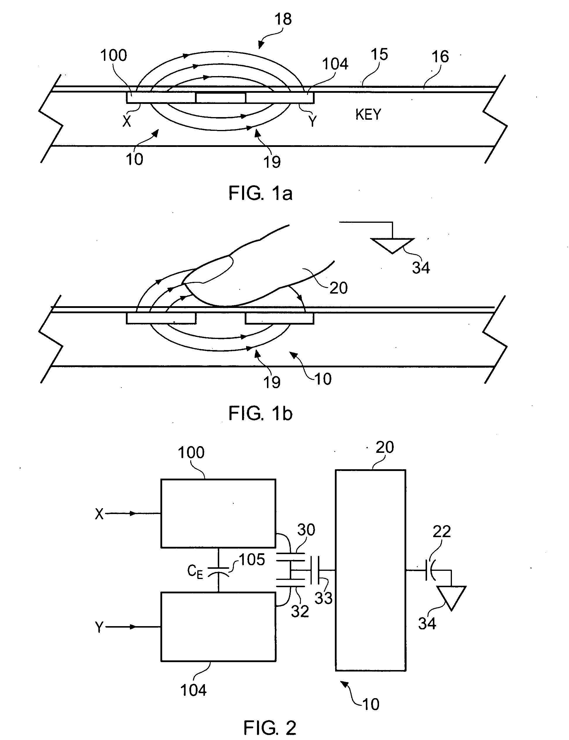
[0038]FIG. 1a is a schematic cross-section through a touch sensitive control panel 15 in the absence of an actuating body, typically a user's finger or stylus.

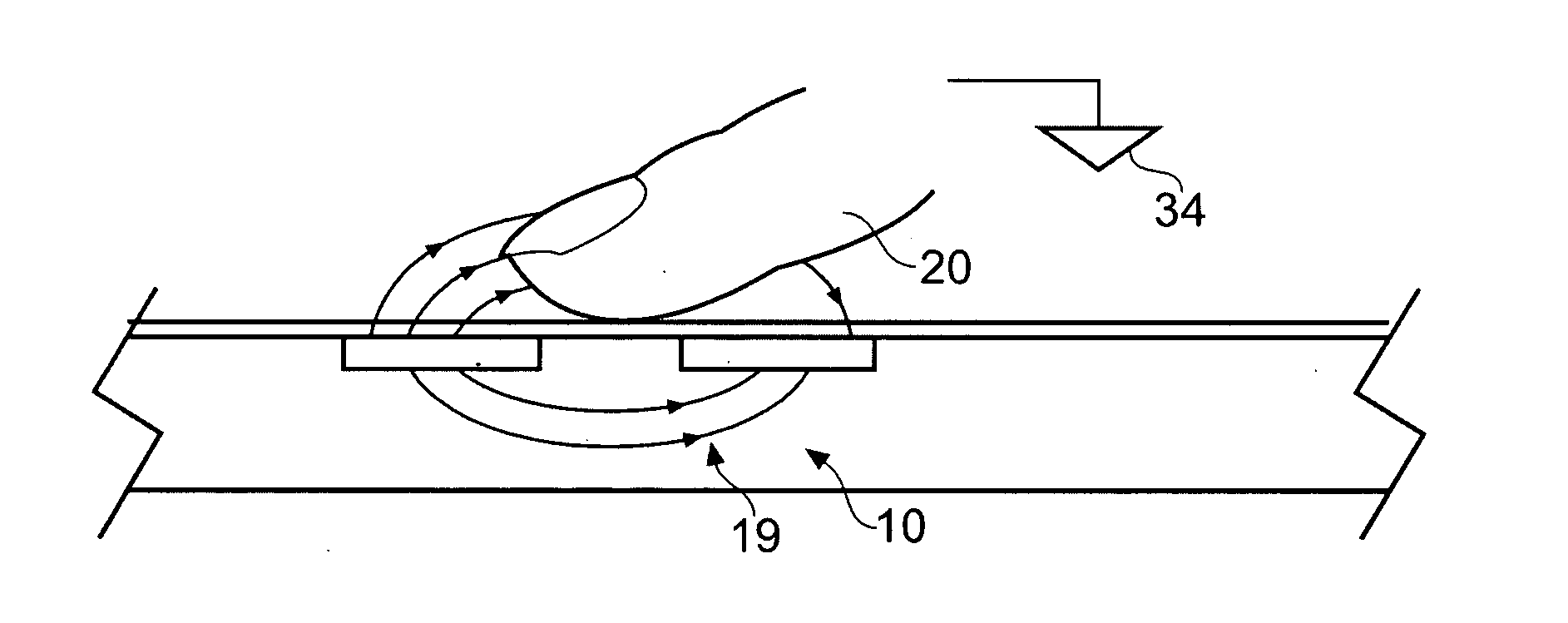
[0039]FIG. 1b corresponds to FIG. 1a, but shows the same cross-section in the presence of an actuating body in the form of a user's finger.

[0040]The touch sensor shown in FIGS. 1a and 1b corresponds to an example in which a pair of transverse electrodes form a touch sensor. As shown in FIG. 1a a pair of electrodes 100, 104 which form a drive or X plate and a receiving or Y plate in the following description are disposed beneath the surface of a touch sensitive control panel 15. The electrodes 100, 104 are disposed beneath a dielectric layer 16, for example a glass or plastics panel. As shown in FIGS. 1a and 1b the touch sensor 10 is arranged to detect the presence of a body such as a user's finger 20 as a result of a change in an amount of charge transferred from the Y plate 104. As shown in FIG. 1a when the X plate 100 is cha...


PUM


Abstract

In a capacitive sensor of the type having X electrodes which are driven and Y electrodes that are used as sense channels connected to charge measurement capacitors, signal measurements are made conventionally by driving the X electrodes to transfer successive packets of charge to the charge measurement capacitors. However, an additional noise measurement is made by emulating or mimicking the signal measurement, but without driving the X electrodes. The packets of charge transferred to the charge accumulation capacitor are then indicative of noise induced on the XY sensing nodes. These noise measurements can be used to configure post-processing of the signal measurements.

Description

BACKGROUND OF THE INVENTION[0001]The present invention relates to noise handling in a capacitive touch sensor for detecting proximity of a body, more especially to a capacitive sensor of the so-called active type which is based on measuring the capacitive coupling between a drive and a sense electrode.[0002]There are various forms of touch sensitive controls which use a capacitive sensor to sense the presence of a body such as a user's finger. A form of touch sensitive control is disclosed in WO-00 / 44018. In this example a pair of electrodes are provided which act as a key so that the presence of a body such as a user's finger is detected as a result of a change in an amount of charge which is transferred between the two electrodes. With this arrangement, one of the electrodes (labeled X) is driven with a drive circuit and the other of the pair of electrodes (labeled Y) is connected to a charge measurement circuit which detects an amount of charge present on the Y plate when driven ...

Claims


Application Information

Patent Timeline
Patent Type & Authority Applications(United States)
IPC IPC(8): G01R27/26
CPCG06F3/0418G01R27/2605G01R29/26G06F3/044G06F3/04184G06F3/0443G06F3/0446
Inventor PHILIPP, HARALDPICKETT, DANIELYILMAZ, ESAT
Owner NEODRON LTD
Why Eureka
Try Eureka