Loop antenna including impedance tuning gap and associated methods

a loop antenna and impedance tuning technology, applied in the field of communication, can solve the problems of inability to orient a radio location tag, or point a cell phone, satellites may tumble unintentionally, and inability to adjust the impedance, so as to reduce the size and cost, and facilitate manufacturing

Active Publication Date: 2010-04-22
HARRIS CORP
View PDF11 Cites 24 Cited by
  • Summary
  • Abstract
  • Description
  • Claims
  • Application Information

AI Technical Summary

Benefits of technology

[0015]In view of the foregoing background, it is therefore an object of the present invention to provide an easily manufactured, reduced size and cost, loop antenna.
[0016]This and other objects, features, and advantages in accordance with the present invention are provided by a loop antenna that may include first and second electrical conductors arranged to define a circular shape with first and second spaced apart gaps therein. The loop antenna may further include opposing portions of the first and second electrical conductors at the first gap defining a signal feedpoint, for example. Opposing portions of the first and second electrical conductors at the second gap may also advantageously define an impedance tuning feature. The second gap may be circumferentially spaced from the first gap less than ninety degrees, for example. The second gap may be greater than the first gap to provide a predetermined impedance and an isotropic radiation pattern at a predetermined operating frequency for the loop antenna. Accordingly, the loop antenna provides an easily manufactured, reduced size, and reduced cost isotropic loop antenna.

Problems solved by technology

It may be impractical to orient a radio location tag, or point a cell phone, and satellites may tumble unintentionally.
When antennas having radiation pattern nulls become misoriented, unacceptable fading is a common problem.
While the high impedance was beneficial for high voltage sparks, high impedances may not be preferential for modern electronics since solid state devices operate at low voltages.
Unfortunately, antennas have not been reduced in size at a comparative level and often are one of the larger components used in a smaller communications device.
However, none of these approaches are focused on providing an isotropic (radiates substantially equally in all directions) planar loop antenna component, e.g. for circuit boards, while being small in size, having desired gain for area, and with an adjustable feed impedance.

Method used


Image

  • Loop antenna including impedance tuning gap and associated methods
  • Loop antenna including impedance tuning gap and associated methods
  • Loop antenna including impedance tuning gap and associated methods

Examples


Embodiment Construction

[0032]The present invention will now be described more fully hereinafter with reference to the accompanying drawings, in which preferred embodiments of the invention are shown. This invention may, however, be embodied in many different forms and should not be construed as limited to the embodiments set forth herein. Rather, these embodiments are provided so that this disclosure will be thorough and complete, and will fully convey the scope of the invention to those skilled in the art. Like numbers refer to like elements throughout, and prime notation is used to indicate similar elements in an alternative embodiment.

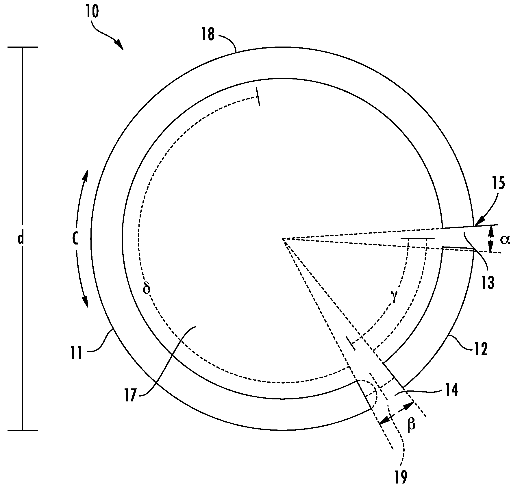
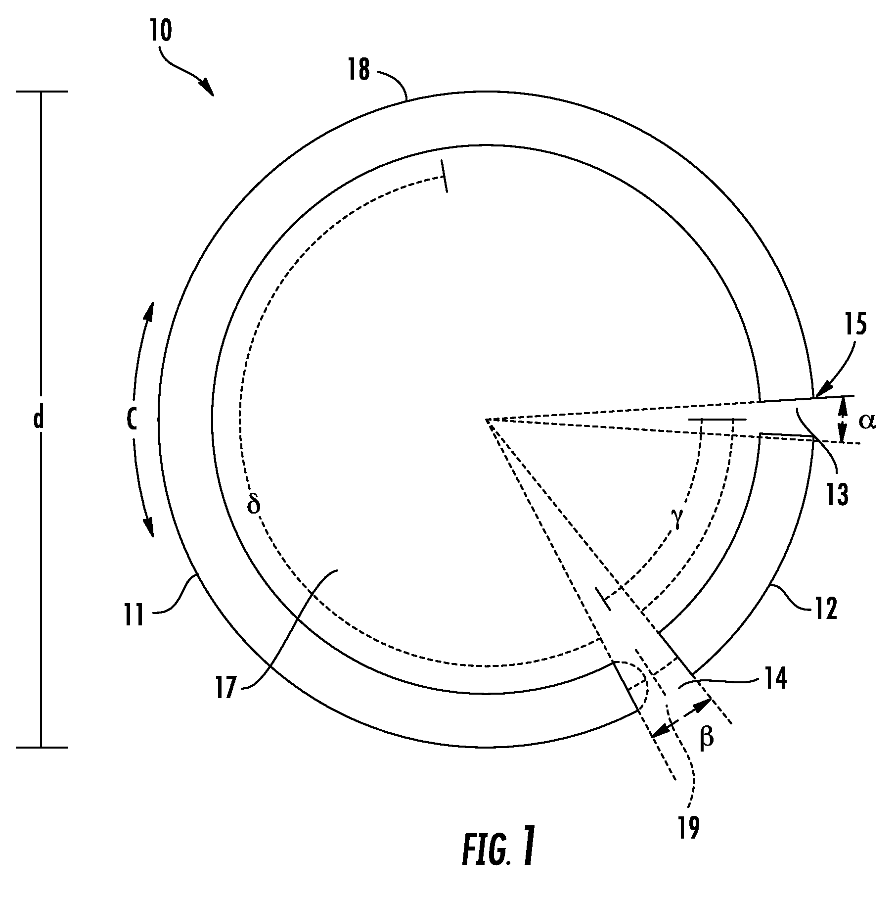
[0033]Referring initially to FIG. 1, a loop antenna 10 includes first and second electrical conductors 11, 12 arranged to define a circular shape with first and second spaced apart gaps 13, 14 therein. The circular shape is configured so that the circumference is equal to a range of 0.3 to 0.6, and more preferably 0.5 times a wavelength of an operating frequency of the lo...


PUM

PropertyMeasurementUnit
angleaaaaaaaaaa
frequenciesaaaaaaaaaa
diameteraaaaaaaaaa

Abstract

A loop antenna may include first and second electrical conductors arranged to define a circular shape with first and second spaced apart gaps therein. Opposing portions of the first and second electrical conductors at the first gap may define a signal feedpoint, and opposing portions of the first and second electrical conductors at the second gap may define an impedance tuning feature. The second gap may be circumferentially spaced from the first gap less than ninety degrees, and the second gap may be greater than the first gap to provide a predetermined impedance. A coaxial transmission line may form a feed inset into the loop conductor. The loop antenna may be planar and have a reduced size for ease of manufacture and use, and it may provide an isotropic radiating pattern at a predetermined operating frequency, which may avoid the need for antenna aiming.

Description

FIELD OF THE INVENTION [0001]The present invention relates to the field of communications, and, more particularly, to antennas and related methods.BACKGROUND OF THE INVENTION [0002]Antennas may be used for a variety of purposes, such as communications or navigation, and portable radio devices may include broadcast receivers, pagers, or radio location devices (“ID tags”). The cellular telephone is an example of a portable communications device, which is nearly ubiquitous. Antennas for portable radios or wireless devices should be small, efficient, and have a broad radiation pattern.[0003]Orientation of a portable device may be a concern. It may be impractical to orient a radio location tag, or point a cell phone, and satellites may tumble unintentionally. When antennas having radiation pattern nulls become misoriented, unacceptable fading is a common problem. Communications need to be reliable, and increased transmitter power may be required. Thus, a nondirectional antenna having a f...

Claims


Application Information

Patent Timeline
Patent Type & Authority Applications(United States)
IPC IPC(8): H01Q11/12H01Q1/24H01P11/00
CPCY10T29/49016H01Q7/005
Inventor PARSCHE, FRANCIS EUGENETEBBE, DENNIS LEE
Owner HARRIS CORP
Why Eureka
Try Eureka