Mobile communication system, mobile station device, base station device, and mobile communication method

a mobile communication system and mobile station technology, applied in the field of mobile communication systems, can solve the problems of radio resource waste, radio resource consumption, radio utilization efficiency falling,

Active Publication Date: 2010-04-22
SHARP KK
View PDF3 Cites 72 Cited by
  • Summary
  • Abstract
  • Description
  • Claims
  • Application Information

AI Technical Summary

Benefits of technology

[0051]In the mobile communication system, the mobile station device, the base station device, and the mobile communication method of the present invention, even if a downlink synchronization error occurs at the mobile station device, it is possible to promptly perform communication with the communication quality in a good state between the base station device and the mobile station device.

Problems solved by technology

The information that a mobile station device transmits to a base station device due to a radio resource request or closed loop control by the abovementioned control (for example, quality information index or packet resending control information, and electric power control information) is, when downlink synchronization is lost, not notified to the base station device, and so closed loop control is not achieved, and there is the possibility of wasting radio resources power consumption.
For that reason, the disagreement interval of this downlink synchronization state is scheduled, and so there is a possibility that the downlink data that is transmitted from the base station device to the mobile station device will not be received, giving rise to the problems of the radio resources being wastefully consumed and the radio utilization efficiency falling.
When a downlink synchronization error occurs in a mobile station device in connection with this, there has been the problem of time being required until being able to perform communication in a state of the communication quality being good between the base station device and the mobile station device.

Method used


Image

  • Mobile communication system, mobile station device, base station device, and mobile communication method
  • Mobile communication system, mobile station device, base station device, and mobile communication method
  • Mobile communication system, mobile station device, base station device, and mobile communication method

Examples


first embodiment

[0097]Next, a mobile communication system in accordance with the first embodiment of the present invention shall be described. The mobile communication system is provided with a mobile station device 10a (refer to FIG. 4 mentioned later) and a base station device 30a (refer to FIG. 5 mentioned later).

[0098]FIG. 4 is a block diagram that shows an example of the composition of the mobile station device 10a in accordance with the first embodiment of the present invention. This mobile station device 10a is provided with a reception portion 11a, a timing tracking portion 12a, a channel demodulation portion 13a, a scheduling portion 14a, a control signal processing portion 15a, a decoding portion 16a, a channel measuring portion 17a, a timing adjusting portion 18a, a CQI calculation portion 19a, an upper layer 20a, a synchronization monitoring portion 21a, an encoding portion 22a, a random access control portion 23a, a channel modulation portion 24a, a transmission power control portion 2...

second embodiment

[0155]Next, a second embodiment of the present invention shall be described. The mobile communication system in accordance with the present embodiment is provided with a mobile station device 10b (refer to FIG. 11 mentioned below) and a base station device 30b (refer to FIG. 12 mentioned below). In the second embodiment, after passing through the downlink synchronization error detection interval, a signal is transmitted by a random access channel from the mobile station device 10b to the base station device 30b.

[0156]FIG. 11 is a block diagram showing an example of the composition of the mobile station device 10b in accordance with the second embodiment of the present invention. This mobile station device 10b is provided with a reception portion 11b, a timing tracking portion 12b, a channel demodulation portion 13b, a scheduling portion 14b, a control signal processing portion 15b, a decoding portion 16b, a channel measuring portion 17b, a timing adjusting portion 18b, a CQI calcul...

third embodiment

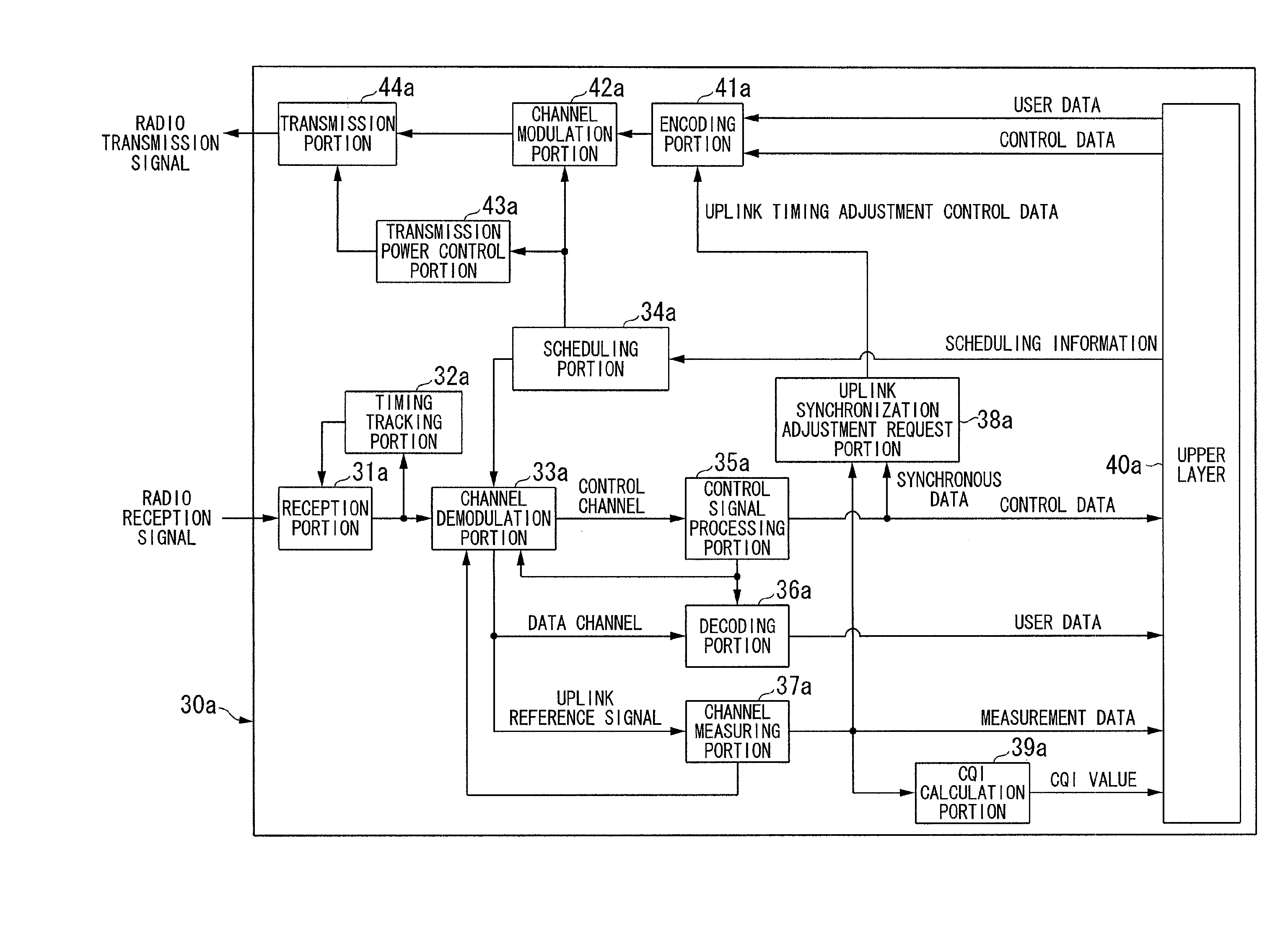
[0188]Next, a third embodiment of the present invention shall be described. The mobile communication system in accordance with the present embodiment is provided with a mobile station device 10c (refer to FIG. 16 mentioned below) and a base station device 30c (refer to FIG. 17 mentioned below).

[0189]In the third embodiment, by utilizing the fact that the downlink synchronization state and the uplink synchronization state of the mobile station device 10c can be independently controlled, it is possible to perform more accurate control on the control of the random access channel that is the uplink transmission channel based on the uplink synchronization state.

[0190]FIG. 16 is a block diagram showing an example of the composition of the mobile station device 10c in accordance with the third embodiment of the present invention. This mobile station device 10c is provided with a reception portion 11c, a timing tracking portion 12c, a channel demodulation portion 13c, a scheduling portion 1...


PUM


Abstract

A mobile station device that communicates with a base station device, including: a downlink synchronization error detecting portion that detects the occurrence of a downlink synchronization error from the measurement result of a transmission signal of the base station device; a synchronization monitoring portion that sets information showing the occurrence of a downlink synchronization error into a random access channel based on the downlink synchronization state or both the downlink and uplink synchronization states of the mobile station device; and a downlink synchronization error notifying portion that transmits the random access channel to the base station device.

Description

TECHNICAL FIELD[0001]The present invention relates to a mobile communication system, a mobile station device, a base station device, and a mobile communication method.[0002]Priority is claimed on Japanese Patent Application No. 2007-063728, filed Mar. 13, 2007, the content of which is incorporated herein by reference.BACKGROUND ART[0003]Currently, by introducing a portion of technology that had been considered for fourth generation systems to the third generation frequency band, the EUTRA (Evolved Universal Terrestrial Radio Access) that aims for an improvement of transmission speed is being studied by the standards group 3GPP (3rd Generation Partnership Project) (refer to Non-Patent Document 1 and Non-Patent Document 2).[0004]The adoption of the OFDMA (Orthogonal Frequency Division Multiplexing Access) system that as a transmission method is resistant to multi-pass interference and suitable for high-speed transmission has been decided in EUTRA. Also, in the detailed specifications ...

Claims


Application Information

Patent Timeline
Patent Type & Authority Applications(United States)
IPC IPC(8): H03M13/09H04W56/00G06F11/07H04W74/08
CPCH04W56/0015H04W92/08H04W74/08H04W56/007
Inventor UEMURA, KATSUNARI
Owner SHARP KK
Why Eureka
Try Eureka