Superconducting cable

a superconducting cable and cable technology, applied in the manufacture/treatment of superconducting devices, permanent superconducting devices, superconducting magnets/coils, etc., to achieve the effect of increasing the current transport capacity of the cable, good protection, and keeping losses

Active Publication Date: 2010-04-22
BRUKER HTS
View PDF8 Cites 19 Cited by
  • Summary
  • Abstract
  • Description
  • Claims
  • Application Information

AI Technical Summary

Benefits of technology

[0009]Superimposing of the two features mentioned above, namely, the usage of two different high Tc materials with different AC losses in different layers of the same cable, together with employment of interruptions of the continuity of the superconducting tape or wire (conductor) across its length allows to ensure a considerable reduction of AC losses, and thus to provide an improved efficiency of AC current / power transportation through the superconducting cable. The inventive improvement is rather surprising since the reduction of the AC losses is provided under increased “ohmic” resistance of the superconducting cable, as there is an additional contribution to the cable resistance originating from the normal conducting interruptions. One may interpret this improvement effect in terms of partial interruptions of eddy currents within each high Tc conductor due to normal conductivity of the interruptions at conditions where AC current is more “pressed” to the outer layer due to the skin-effect.
[0011]Further, the invention proposes to introduce normal conducting interruptions within the conductors of the outer layer (or some outer layers). In other words, the superconducting path within each conductor of the outer layer (or the outer layers) is broken, typically with a regular spacing of the interruptions. The interruptions prevent the formation of far extending eddy current loops based on superconductivity within the conductors, what reduces AC losses. The non-superconducting interruptions introduce some current transport losses, too, but typically these losses turn out to be considerably smaller than the avoided AC losses due to eddy currents. To this end, the number and spacings of the normal-conducting interruptions may be optimized with respect to the total cable losses, also in view of the respective contributions of the inner and outer layers to the total AC current at a selected frequency.
[0012]In accordance with the invention, the layers are typically helically wound on the support structure, and on top of each other. In between the support structure and the layers an intermediate structure comprising e.g. normally conducting tapes may be employed. The terms “inner” and “outer” refer to the radial position of a layer within the cable, which is typically basically axially symmetric. When there are more than two layers (in particular within a line, i.e. within layers of a particular direction of current transport), there may be two or more outer layers and / or two or more inner layers. Note that by a larger number of layers, the overall current transport capacity of the cable may be increased.
[0013]In a preferred embodiment of the inventive superconducting cable, the normal-conducting interruptions in a high Tc conductor are separated by a distance of between 2 m to 40 m. Typically, the separation of the interruptions in a conductor is periodic. The above mentioned distance intervals have been found to offer good protection from eddy currents while still keeping losses (due to normal conducting interruptions) low with typical AC frequencies used with superconducting cables.

Problems solved by technology

The non-superconducting interruptions introduce some current transport losses, too, but typically these losses turn out to be considerably smaller than the avoided AC losses due to eddy currents.

Method used


Image

  • Superconducting cable
  • Superconducting cable
  • Superconducting cable

Examples


first embodiment

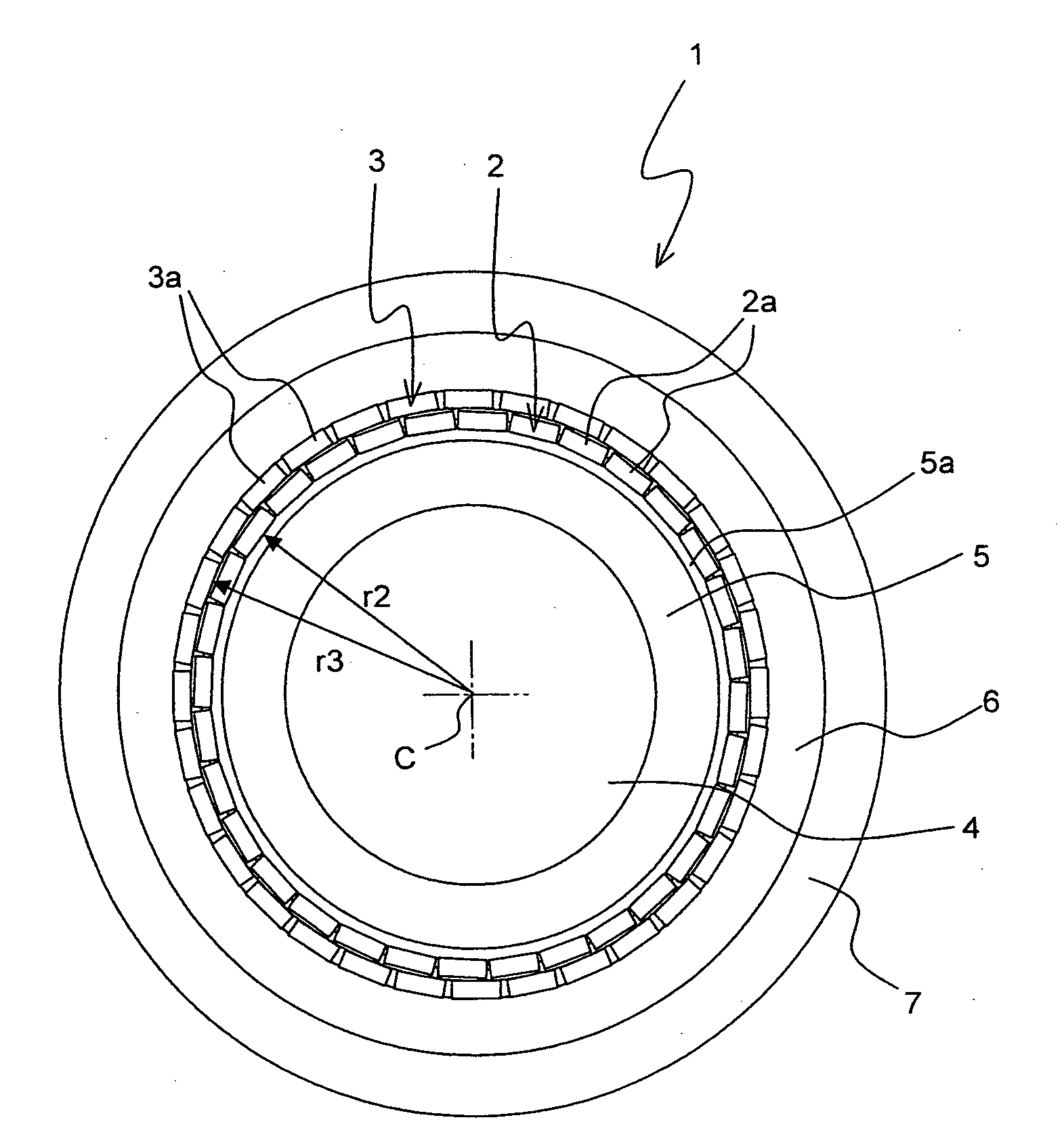
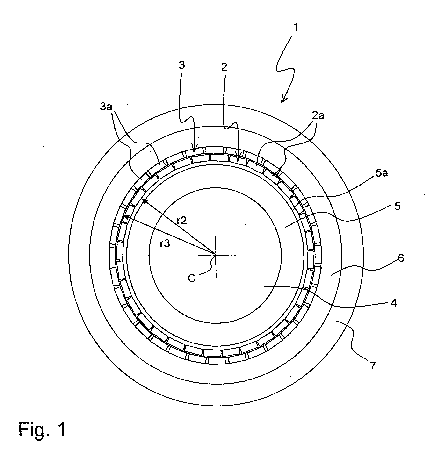
[0028]FIG. 1 shows an inventive superconducting cable 1 in a schematic cross-section, perpendicular to the cable axis along which the cable structure is basically invariant (note the twist illustrated in FIG. 4, though).

[0029]The cable 1 comprises two layers 2, 3 of conductors 2a, 3a with a high Tc (critical temperature, below which the conductor has superconductive properties). Note that preferably Tc of all conductors 2a, 3a, in accordance with the invention, is above 77 K. The conductors 2a of the inner layer 2, here a number of 32 conductors 2a, are all arranged in a ring shape on the same radius r2 of the cable 1 with respect to the cable center C, with respect to which the cable 1 is basically axially symmetric. The conductors 3a of the outer layer 3 are correspondingly all on the same radius r3, with r3>r2.

[0030]The conductors 3a of the outer layer 3 are here tapes, namely coated conductors with a stainless steel substrate on which YBCO has been deposited. So YBCO acts as the...

second embodiment

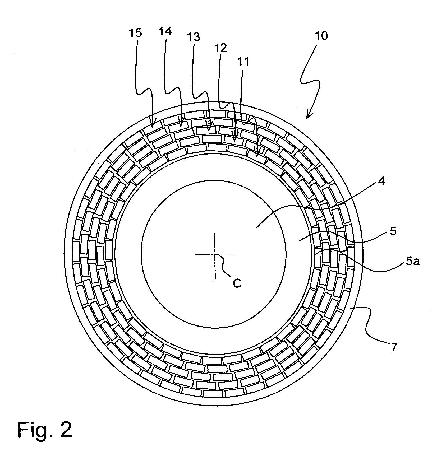
[0036]FIG. 2 shows an inventive superconducting cable 10.

[0037]It comprises altogether five layers 11-15 of high Tc conductors. The two innermost layers 11 and 12 comprise conductors of BSCCO and can be considered as inner layers in accordance with the invention, whereas the three outermost layers 13, 14 and 15 comprise YBCO and can be considered as outer layers in accordance with the invention. Further, the cable 10 comprises a tubular dielectric support structure 5 and a shunt metal element 5a again, on which the layers 11-15 are supported. The cavity within the support structure 5 acts as a channel 4 for a coolant again. The outermost layer 15 is covered with a dielectric insulation 7, which comprises here thick plastic tapes (not shown in detail).

[0038]When AC current is transported through the layers 11-15, the layers farther away from the center C experience a higher current amplitude. In accordance with the invention, these outer layers 13, 14 and 15 comprise YBCO material wh...


PUM

PropertyMeasurementUnit
distanceaaaaaaaaaa
AC frequenciesaaaaaaaaaa
frequenciesaaaaaaaaaa

Abstract

A superconducting cable (1; 10; 30) has a channel (4, 38) for a cooling liquid, a tubular support structure (5, 37), at least two layers (2, 3; 11-15; 31, 32, 35, 36) comprising high Tc conductors (2a, 3a) which comprise a high Tc material, and an insulation (7, 17), in particular a tubular insulation (7). The conductors (3a) of the outer layer (3; 13-15; 33, 36) comprise a first high Tc material that is different from a second high Tc material of the conductors (2a) of the inner layer (2; 11-12; 32, 35), wherein the first high Tc material exhibits lower AC losses as compared the second high Tc material, and that the high Tc conductors (3a) of the outer layer (3; 13-15; 33, 36) comprise normal-conducting interruptions (41, 42, 43). The superconducting cable exhibits reduced AC losses.

Description

[0001]This application claims Paris Convention priority of EP 08 012 411.8 filed Jul. 9, 2008 the complete disclosure of which is hereby incorporated by reference.BACKGROUND OF THE INVENTION[0002]The invention relates to a superconducting cable, comprising a channel for a cooling liquid, a tubular support structure, at least two layers comprising high Tc conductors which comprise a high Tc material, and an insulation, in particular a tubular insulation.[0003]Such a superconducting cable is known from EP 0 623 937 A2, for example.[0004]Superconducting cables are aimed for transporting large currents with a minimum of losses. In general, superconducting cables offer superconducting current paths with a vanishing ohmic resistance. The superconductor material used in superconducting cables must be cooled cryogenically, though. In practice, superconductor materials with a high critical temperature (Tc) are preferred for superconducting cables, such that cooling is possible with inexpensi...

Claims


Application Information

Patent Timeline
Patent Type & Authority Applications(United States)
IPC IPC(8): H01B12/02
CPCH01B12/06Y10T29/49014Y02E40/642Y02E40/60
Inventor USOSKIN, ALEXANDER
Owner BRUKER HTS
Why Eureka
Try Eureka