Imaging apparatus and drive recorder system

a drive recorder and drive recorder technology, applied in the field of imaging apparatus and drive recorder system, can solve the problems of being difficult for a driver to personally confirm the contents of image data, clever fraud committed, etc., and achieve the effect of improving the maintainability of image data

Inactive Publication Date: 2010-04-22
NIKON CORP
View PDF11 Cites 29 Cited by
  • Summary
  • Abstract
  • Description
  • Claims
  • Application Information

AI Technical Summary

Benefits of technology

[0013]According to the present invention, recording two sets of accident image data which photograph the same accident situation at an accident occurrence improves maintainability of image data. Also, out of respective sets of accident image data, credibility as evidence is secured by accident image data with a higher security level and a driver can personally confirm contents of the image data by accident image data with a lower security level.

Problems solved by technology

Therefore, there is also a possibility that fraudulence is committed cleverly by unit which modifies a picture of an accident by editing image data to be used for evidence.
While credibility of image data as evidence is enhanced according to the Patent Document 1, no one but a specific person (public organization, insurance company, or the like), who has a decoding key can decode the image data, and therefore it becomes difficult for a driver personally to confirm contents of the image data.

Method used


Image

  • Imaging apparatus and drive recorder system
  • Imaging apparatus and drive recorder system
  • Imaging apparatus and drive recorder system

Examples


first embodiment

Description of a First Embodiment

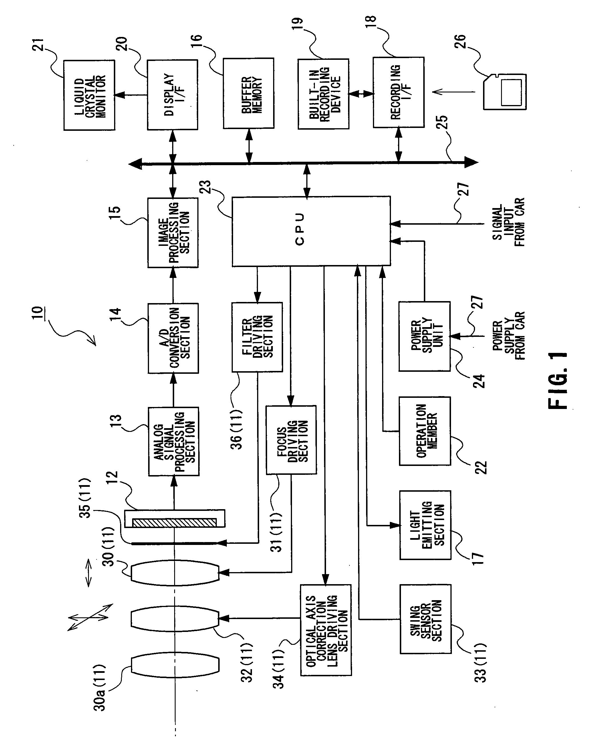
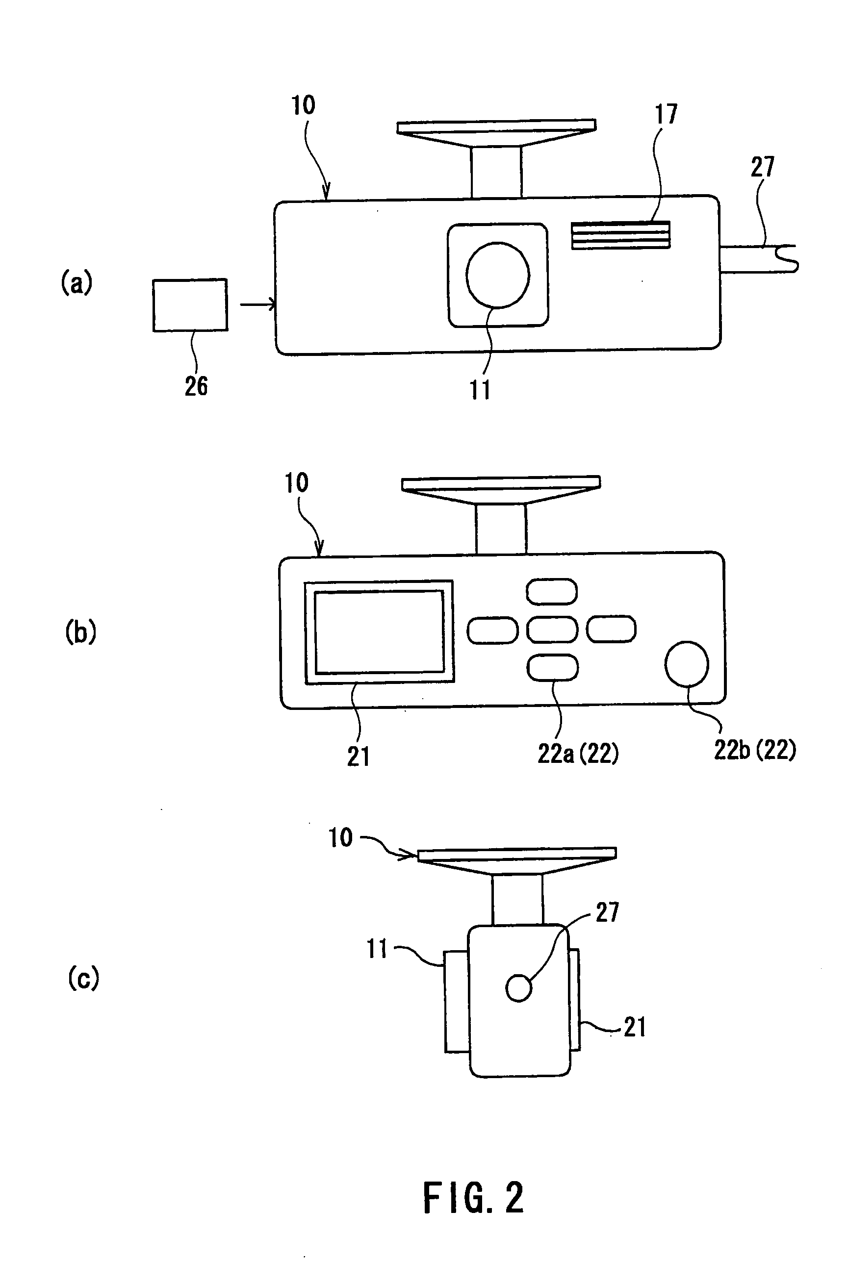
[0024]FIG. 1 is a block diagram showing a configuration of a drive recorder camera according to a first embodiment. FIG. 2 is an appearance view of the drive recorder camera and FIG. 3 is a diagram showing an attached state of the drive recorder camera.

[0025]A drive recorder camera 10 according to the first embodiment is attached to a position in a car, from which an area including a viewing field ahead of a driver's seat can be photographed, (for example, near a rearview mirror in the car). Then, the drive recorder camera 10 can photograph an image around the car during car driving (refer to FIG. 3). As shown in FIG. 2A, a photographic optical system 11 and a light emitting section 17 are disposed on the front side of a housing of the drive recorder camera 10. Also, as shown in FIG. 2B, a liquid crystal monitor 21, and an operation switch 22a and a release button 22b forming an operation member 22 are disposed on the rear side of the housing of the ...

second embodiment

Description of a Second Embodiment

[0077]FIG. 8 is a block diagram showing a configuration of a drive recorder camera according to a second embodiment. Note that common constituents in the following embodiments and in the first embodiment are denoted by the same symbols and redundant descriptions will be omitted.

[0078]The second embodiment is a variation of the first embodiment, and the data bus 25 is further connected to a communication section 40. The communication section 40 transmits accident image data to an accident image management server which is managed by a public organization, an insurance company, or the like using a publicly known radio communication channel (e.g., communication channel between a mobile phone and each base station).

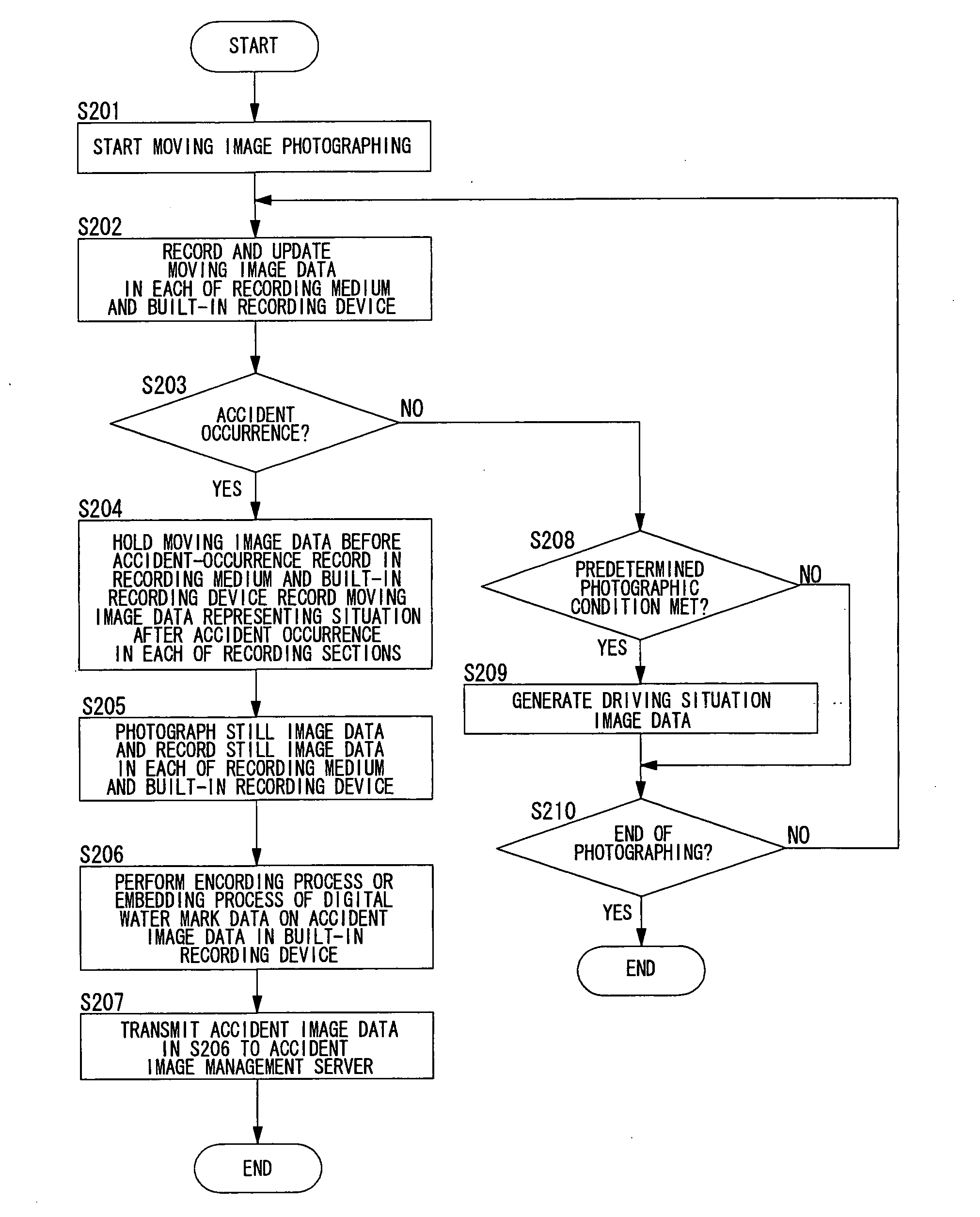
[0079]FIG. 9 is a flow chart showing an operation of the drive recorder camera according to the second embodiment. Here, S201 to S205 in FIGS. 9 correspond to S101 to S105 in FIG. 5, and S208 to S210 in FIG. 9 correspond to S107 to S109 in FIG...


PUM


Abstract

An imaging apparatus mounted on a vehicle and imaging a vicinity of the vehicle, includes a photographic lens, an image pickup device, an accident detection sensor, an image processing section, and a recording section. The image pickup device generates an image signal by performing photoelectric conversion of an object image based on a light flux from the photographic lens. The accident detection sensor detects an accident occurrence based on a shock to the vehicle. The image processing section generates first accident image data and second accident image data which photograph the same accident situation at an accident occurrence, based on the image signal. The recording section records the first accident image data and the second accident image data in different states of security levels regarding data credibility, respectively.

Description

TECHNICAL FIELD[0001]The present invention relates to an imaging apparatus and a drive recorder system mounted on a vehicle for imaging and recording a vicinity of the vehicle at an accident.BACKGROUND ART[0002]Conventionally, there has been proposed a drive recorder which mounts a camera capable of photographing a moving image on a vehicle and records a picture at an accident. Image data in the drive recorder is digital data and has a feature of being easily edited with a computer. Therefore, there is also a possibility that fraudulence is committed cleverly by unit which modifies a picture of an accident by editing image data to be used for evidence. Hence, a drive recorder is disclosed in a Patent Document 1, which encodes and records data to enhance credibility of image data as evidence.[0003]While credibility of image data as evidence is enhanced according to the Patent Document 1, no one but a specific person (public organization, insurance company, or the like), who has a dec...

Claims


Application Information

Patent Timeline
Patent Type & Authority Applications(United States)
IPC IPC(8): B62D41/00G06F7/00H04N7/18
CPCB60W2030/082H04N21/442B62D41/00G07C5/0891H04N5/23203H04N5/23248H04N5/23258H04N5/23287H04N5/772H04N5/781H04N5/85H04N5/907H04N9/7921H04N9/8205H04N21/41422H04N21/42202H04N21/4223H04N21/4334B60W2420/42H04N23/66H04N23/68H04N23/6812H04N23/687
Inventor FUJINAWA, NOBUHIRONOZAKI, HIROTAKEMITSUHASHI, SETSU
Owner NIKON CORP
Why Eureka
Try Eureka