Audio encoding apparatus, audio decoding apparatus, and audio encoded information transmitting apparatus

a technology of information transmitting apparatus and audio encoding, which is applied in the field of audio encoding apparatus, audio decoding apparatus, and audio encoded information transmitting apparatus, can solve the problems of not being suitable for a high-quality signal, and achieve the effects of increasing the amount of information that can be viewed/listened to by an individual, high-speed audio reproduction, and high practical value of the present invention

Active Publication Date: 2010-04-22
PANASONIC CORP
View PDF14 Cites 17 Cited by
  • Summary
  • Abstract
  • Description
  • Claims
  • Application Information

AI Technical Summary

Benefits of technology

[0043]As is clear from the above-mentioned description, the audio encoding apparatus, audio decoding apparatus, and audio encoded information transmitting apparatus according to the present invention, produces the effect of enabling the information transmission amount to be reduced to the same level as that of the normal bit rate, and the processing amount in decoding to be reduced to the same level as that in normal decoding.
[0044]Accordingly, with

Problems solved by technology

This is because the second method is only used in low-qual

Method used


Image

  • Audio encoding apparatus, audio decoding apparatus, and audio encoded information transmitting apparatus
  • Audio encoding apparatus, audio decoding apparatus, and audio encoded information transmitting apparatus
  • Audio encoding apparatus, audio decoding apparatus, and audio encoded information transmitting apparatus

Examples


first embodiment

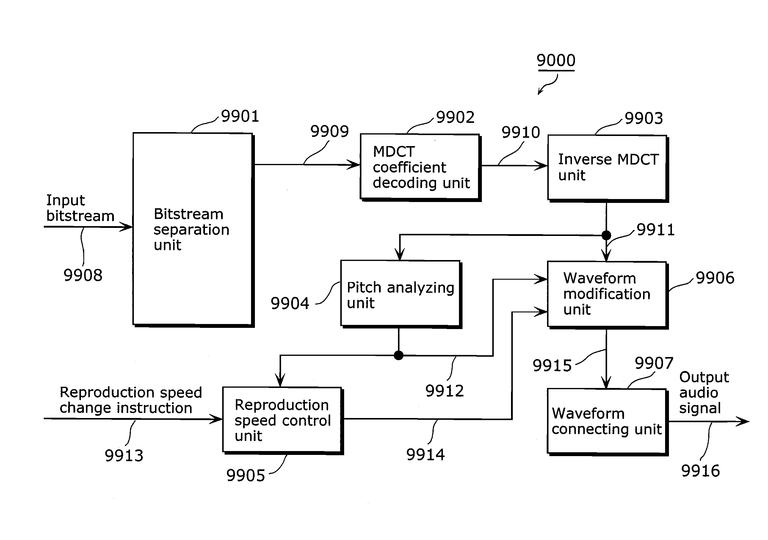
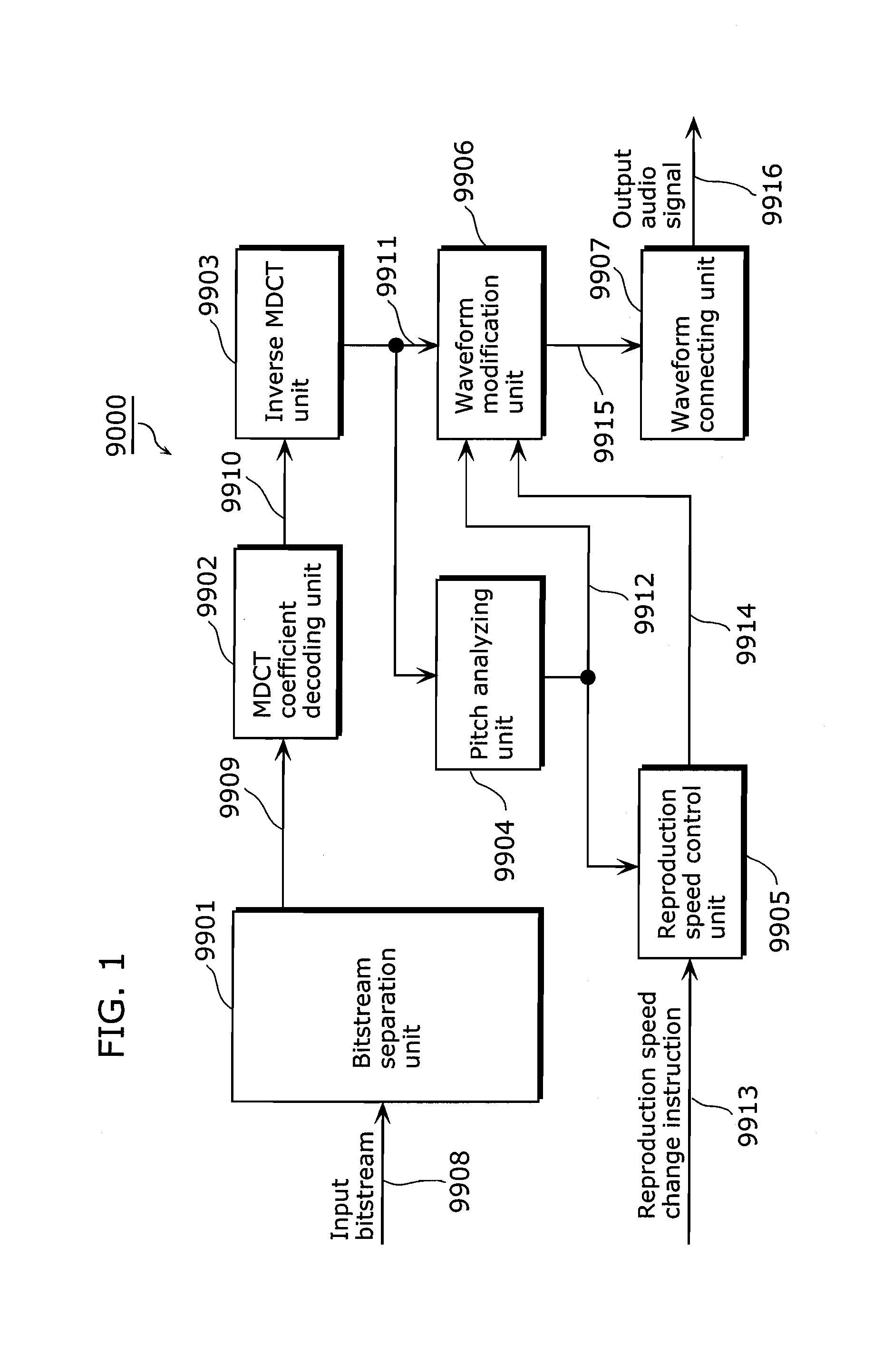
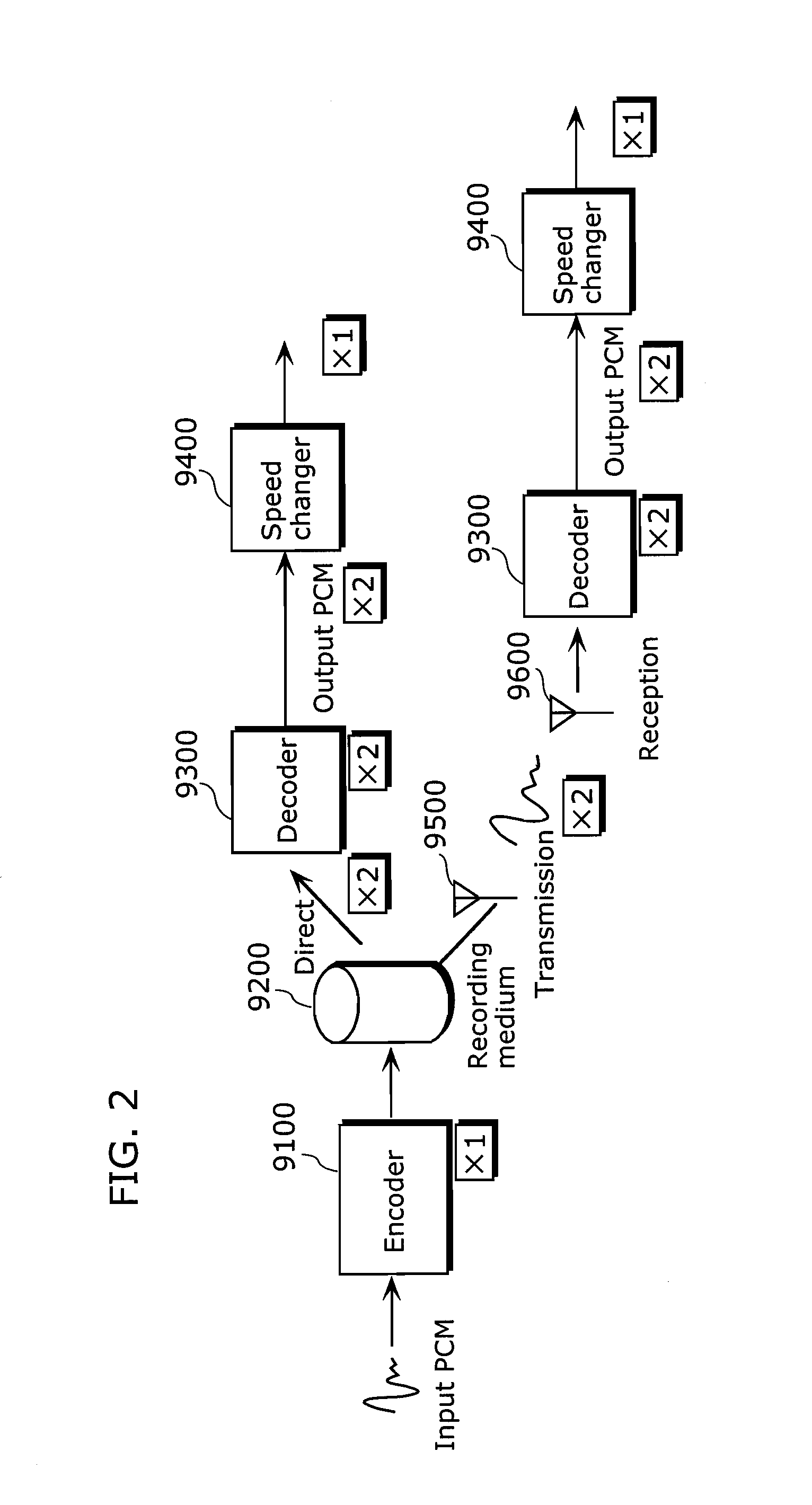
[0088]FIG. 3 is a function block diagram showing the configuration of the audio encoding apparatus in the present embodiment of the present invention. Note that the following description shows an example which uses MDCT for temporal frequency transformation. However, MDCT is an example of a transformation algorithm based on Time Domain Aliasing Cancellation (TDAC) Patent Reference 2 technology, and any temporal frequency transformation based on TDAC technology can be used in place of MDCT. In addition, encoding apparatus 10 is used in place of the encoder 9100 in the system in FIG. 2.

[0089]The encoding apparatus 10 is an apparatus which performs compression encoding on a digitalized audio signal such as PCM while modifying it in order to be able to respond to variable-speed reproduction. As shown in FIG. 1, the encoding apparatus 10 includes a framing unit 101, a pitch detection unit 102, a waveform modification unit 103, an MDCT unit 104, an MDCT coefficient encoding unit 105, and ...

second embodiment

[0174]In the encoding and decoding apparatuses of the present invention, the relationship of the coded frame length N and the pitch cycle L is important.

[0175]For example, in the case where the L>N relationship is upheld, application with the technique in the first embodiment is not possible. Furthermore, when L becomes extremely small in relation to N, overlapping sections increase relatively, triggering the decrease in encoding efficiency.

[0176]In order to solve this problem, the second embodiment shows a configuration that can be applied even in the case where L>N or an odd number of the pitch waveform signal exists in the MDCT frame of 2N samples.

[0177]FIG. 12 is a function block diagram showing the configuration of an encoding apparatus 12 related to the second embodiment.

[0178]In contrast to the configuration of the encoding apparatus 10 shown in FIG. 3, the encoding apparatus 12 includes a second waveform modification unit 1001 in place of the waveform modification unit 103, ...

third embodiment

[0193]FIG. 15 is a diagram showing the configuration of the audio encoding apparatus in the third embodiment.

[0194]As shown in FIG. 15, in contrast to the encoding apparatus 11 in FIG. 11, an encoding apparatus 13 is different in terms of being provided with a third waveform modification unit 1301 in place of the waveform modification unit 103, and inputting the adjusted pitch cycle 902 to the third waveform modification unit 1301; being provided with a new frame identifier generation unit 1302, and generating a frame identifier 1305 based on frame skip information outputted from the third waveform modification unit 1301; and inputting a second pitch cycle 1303, outputted by the third waveform modification unit 1301, and the frame identifier 1305 to the bitstream multiplex unit 106.

[0195]The frame skip information 1304, the frame identifier 1305 which are additional functions in the present configuration, and the operation of the third waveform modification unit 1301 and the frame i...


PUM


Abstract

To reduce the amount of transmitted information and further reduce the processing amount at a decoding apparatus. An encoding apparatus (10), which has an MDCT part (104) for converting an input audio signal to a frequency parameter by unit of a predetermined time/frequency conversion frame length and an MDCT coefficient encoding part (105) for encoding the frequency parameter, comprises a pitch detecting part (102) that detects the pitch period of an audio signal; a framing part (101) that frames, based on the detected pitch period, the input audio signal; a waveform deforming part (103) that deforms, based on the pitch period, the waveform of the framed audio signal in accordance with the time/frequency conversion frame length, and outputs the audio signal the waveform of which has been deformed, to the MDCT part (104); and a bitstream multiplexing part (106) that multiplexes the pitch period and the frequency parameter encoded by the MDCT coefficient encoding part (105) and outputs the resultant as a bitstream.

Description

TECHNICAL FIELD [0001]The present invention relates to an audio encoding apparatus, an audio decoding apparatus, and an audio encoded information transmitting apparatus, and particularly to a technique for efficiently encoding an audio signal into a small amount of information while responding to changes in reproduction speed during listening, and for decoding encoded information.BACKGROUND ART[0002]The objective of audio encoding is compression encoding a digitalized signal as effectively as possible, transmitting this, and reproducing an audio signal of the highest possible quality through the decoding by a decoder.[0003]Various methods have been proposed as audio encoding methods, depending on the conditions such as the type of the signal to be encoded, the bit rate, and required sound quality. For example, MPEG-4 Audio which is an ISO / IEC standard specification (see Non-patent Reference 1) discloses encoding methods such as Advanced Audio Coding (AAC), Code Excited Linear Predic...

Claims


Application Information

Patent Timeline
IPC IPC(8): G10L19/02G10L19/022G10L19/025G10L19/09G10L19/097G10L21/045G10L25/90
CPCG10L19/022G10L21/04G10L19/097G10L19/09
Inventor TANAKA, NAOYA
Owner PANASONIC CORP
Why Eureka
Try Eureka