Device and method for increasing evaporation rates of blow-down apparatus

a technology of evaporation rate and blowdown apparatus, which is applied in the direction of laboratory glassware, separation processes, furnaces, etc., can solve problems such as inability to achiev

Inactive Publication Date: 2010-04-29
BANK OF AMERICA N A
View PDF5 Cites 4 Cited by
  • Summary
  • Abstract
  • Description
  • Claims
  • Application Information

AI Technical Summary

Benefits of technology

[0009]The present discloses an insert for a liquid holding container. The insert includes a frame sized to fit snugly but smoothly into an opening into and along at least part of the length of the container. The top end of the frame includes a top vane that is wider than the container opening, so that the insert when inserted into the container comes to rest with the top vane resting on the container opening. Vane are spaced apart and attached along the frame and extend, at least partially, from one side to the opposite side of an internal width of the container and are distributed along the length of the frame at a tilt angle and a pitch angle. The pitch enables a first passage for the incoming gas to flow in a laminar fashion through and reach the surface of a liquid held in the container and then to return via a second passage on the other side of the frame and exit via the container opening. The tilt angle prevents a vane that might be partially immersed in the liquid from fully blocking the path connecting the first and the second passages.

Problems solved by technology

A laminar high volume flow of blow-down gas striking the surface 10 of the liquid is the goal, but it may not be achieved due to the turbulence.

Method used


Image

  • Device and method for increasing evaporation rates of blow-down apparatus
  • Device and method for increasing evaporation rates of blow-down apparatus
  • Device and method for increasing evaporation rates of blow-down apparatus

Examples


Embodiment Construction

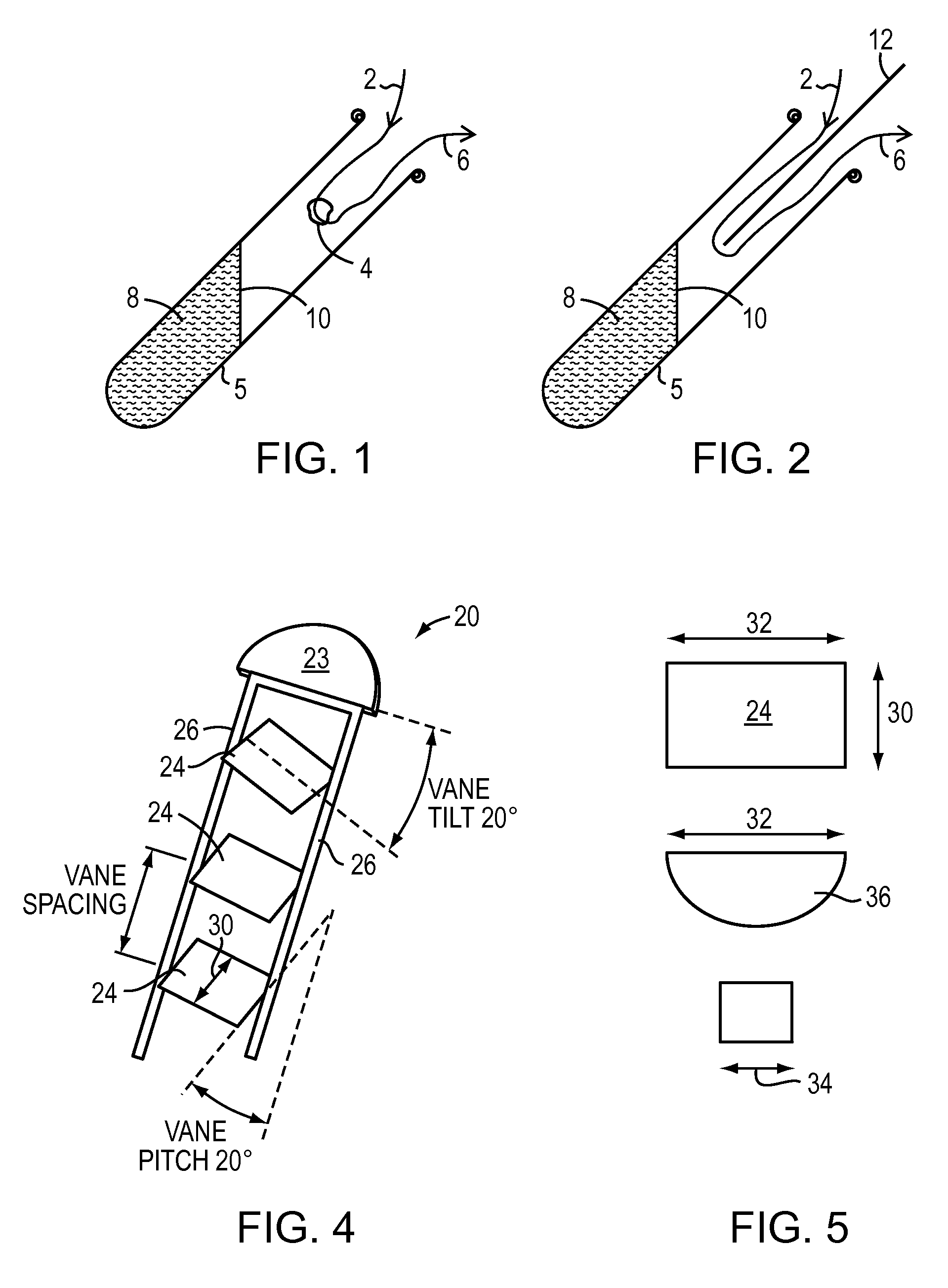
[0021]FIG. 2 shows a baffle 12 inserted into the test tube 5. Here the incoming gas is directed down to the surface 10 and back out 6 on the other side of the baffle 10 without the turbulence of FIG. 1. However, as the liquid 8 evaporates and is carried away by the exiting gas 6, the surface 10 retreats from the end of the baffle and the turbulence returns at the end of the baffle 12.

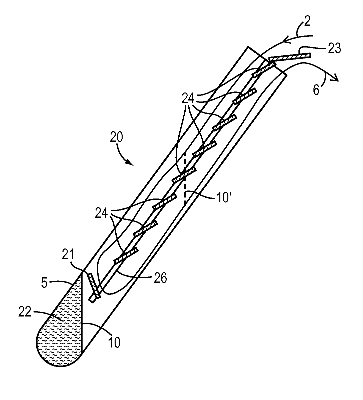
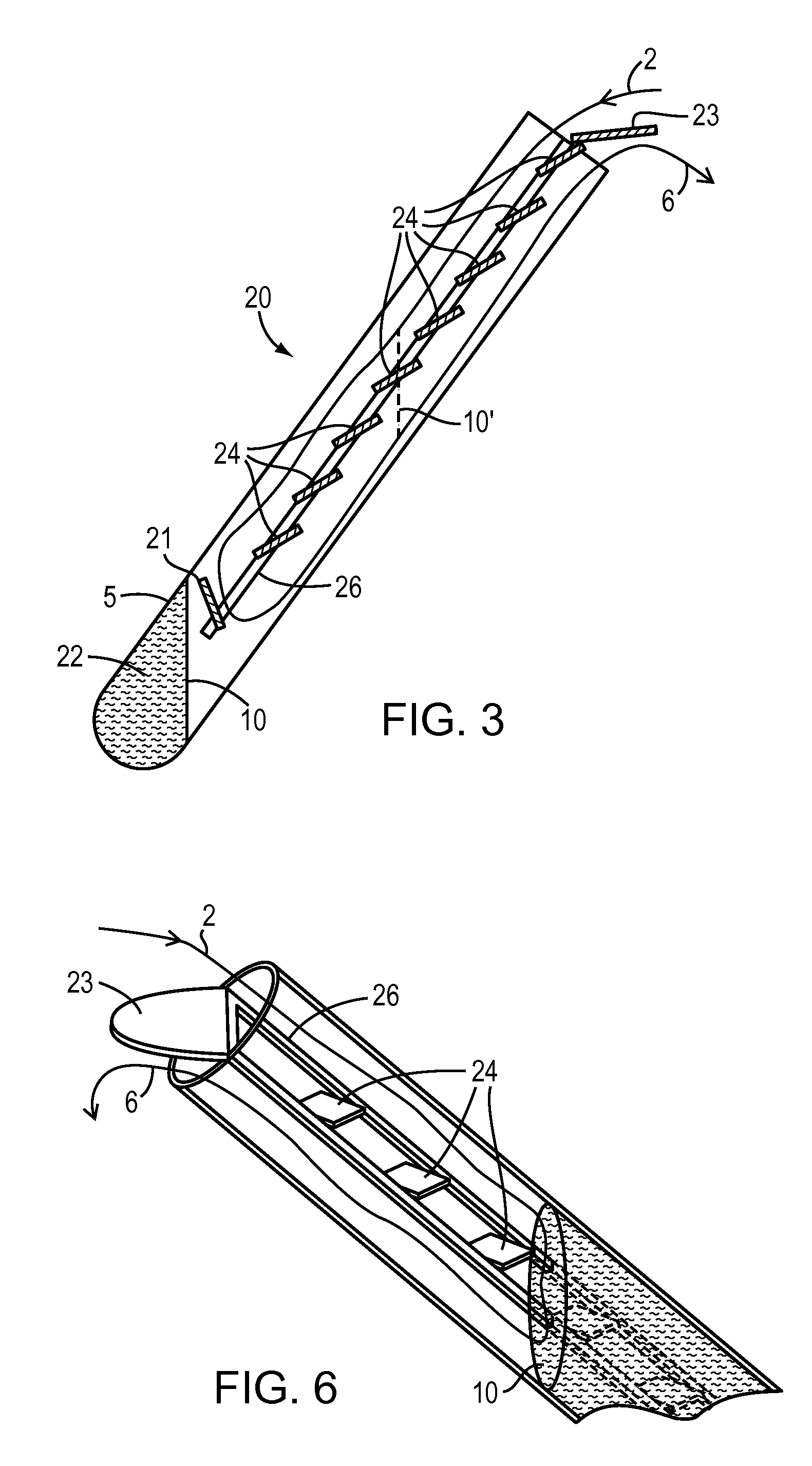
[0022]The FIG. 3 insert 20 may extend to the bottom of the test tube 5. But in FIG. 3 the insert ends with a stopping vane 21 located before the bottom. The stopping vane prevents the drying gas flow 2 from reaching the liquid surface 10 when only a small amount of liquid 22 remains at the bottom of the test tube. The top vane 23 is wider than the test tube opening and so rests on test tube and defines how far the insert may extend into the test tube. The top vane 23 is angled to divert the exiting gas 6 away from the entering gas 2.

[0023]The insert 20 has a frame 26 having two parallel rails that each ...


PUM


Abstract

This disclosure reveals a combination of embodiments that increase the evaporation rate of liquid solutions when subjected to blow-down gas flows. Certain gas flow separator baffles or framed inserts with vanes may be especially effective to enhance evaporation when combined with aggressive blow-down flow rates and centrifugal force. The centrifugal force applied to the evaporating liquid protects sample integrity by preventing the solution(s) from splashing out of the drying container. Such splashing, when high blow-down gas flow rates are directed into the sample containers, affects yield and purity.

Description

CROSS-REFERENCE TO RELATED APPLICATIONS[0001]The present application claims the benefit of U.S. Provisional Patent Application Ser. No. 61 / 108,162, which was filed on Oct. 24, 2008. This provisional application is of common inventorship and ownership, and is hereby incorporated herein by reference.BACKGROUND OF THE INVENTION[0002]1. Field of the Invention[0003]The present disclosure relates to an apparatus and a method for increasing evaporation rates of solutions within sample containers subjected to a drying gas flowing into the sample container.[0004]2. Background Information[0005]Sample concentrators are prevalent in processing liquid solutions containing a sample material or materials of interest. Materials of interest are typically synthesized, modified, and purified, in solution-based process steps. To recover these dissolved non-volatile materials as dry powders, or to increase the concentration of compounds, vacuum centrifuges, freeze drying, and blow down concentrators are...

Claims


Application Information

Patent Timeline
Patent Type & Authority Applications(United States)
IPC IPC(8): B01D1/14B01D3/00F26B3/06F26B19/00F26B25/08
CPCB01D1/14B01D1/30B01L3/5082G01N2001/4027B01L2300/0609G01N1/40B01L2200/0678
Inventor HEDBERG, HERBERT J.KANGAS, BRIAN A.BURNS, MICHAEL A.
Owner BANK OF AMERICA N A
Why Eureka
Try Eureka