Bonding of cutters in diamond drill bits

a diamond drill bit and cutter technology, applied in cutting machines, manufacturing tools, other chemical processes, etc., can solve the problems of low brazing strength between the cutting elements and the bit body, early failure of the bit, etc., and achieve the effect of improving the brazing strength

Inactive Publication Date: 2010-04-29
SMITH INT INC
View PDF12 Cites 10 Cited by
  • Summary
  • Abstract
  • Description
  • Claims
  • Application Information

AI Technical Summary

Benefits of technology

[0010]In another exemplary embodiment, the present invention provides a method for improving the braze strength between a cutting element and a drill bit body. The method includes forming a bit body having at least one region formed of a matrix material impregnated with superabrasive material and forming a pocket extending into the region. The pocket includes an inner surface lined with a layer of a matrix material that is substantially superabrasive-free. The method may further comprise brazing a cutting element to the inner surface of the pocket.

Problems solved by technology

The presence of superabrasive materials in the impregnated matrix material, however, lowers the braze strength between the cutting elements and the bit body, more particularly, between the cutting element and the cavity to which the cutting element is joined by brazing.
If the braze strength is weak, the cutting elements are prone to becoming disengaged from the bit body during drilling, causing early failure of the bit.

Method used


Image

  • Bonding of cutters in diamond drill bits
  • Bonding of cutters in diamond drill bits
  • Bonding of cutters in diamond drill bits

Examples


Embodiment Construction

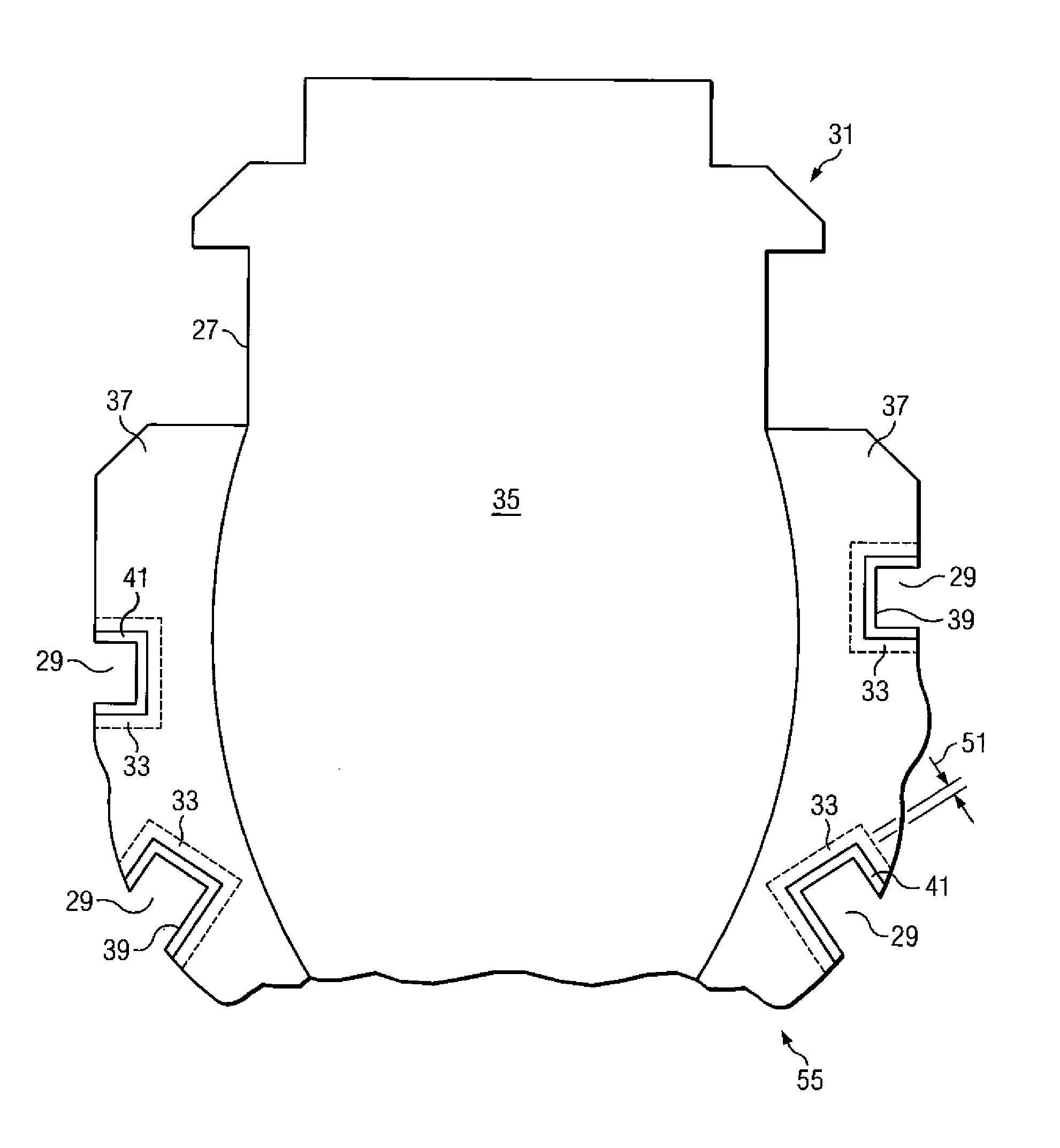
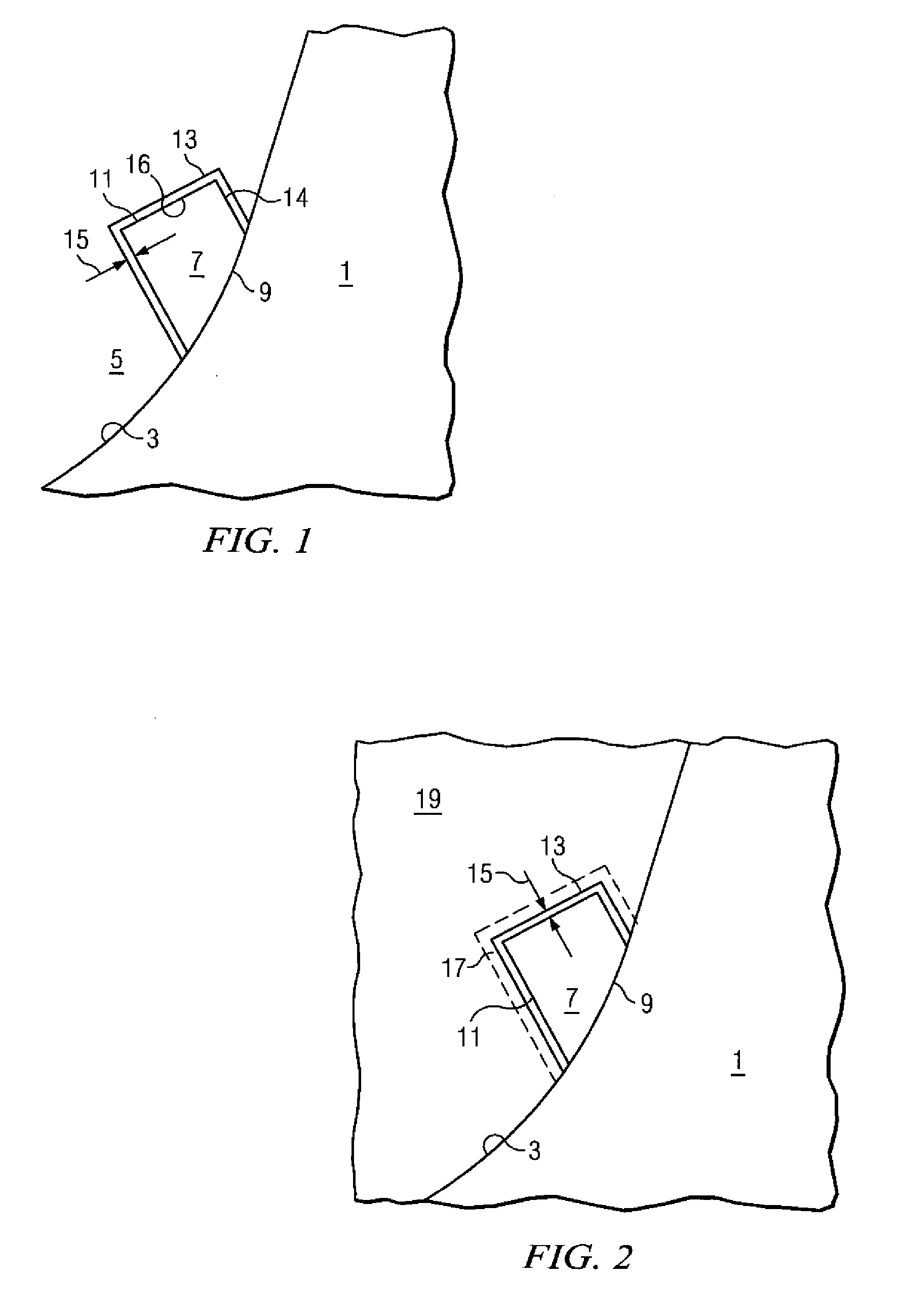
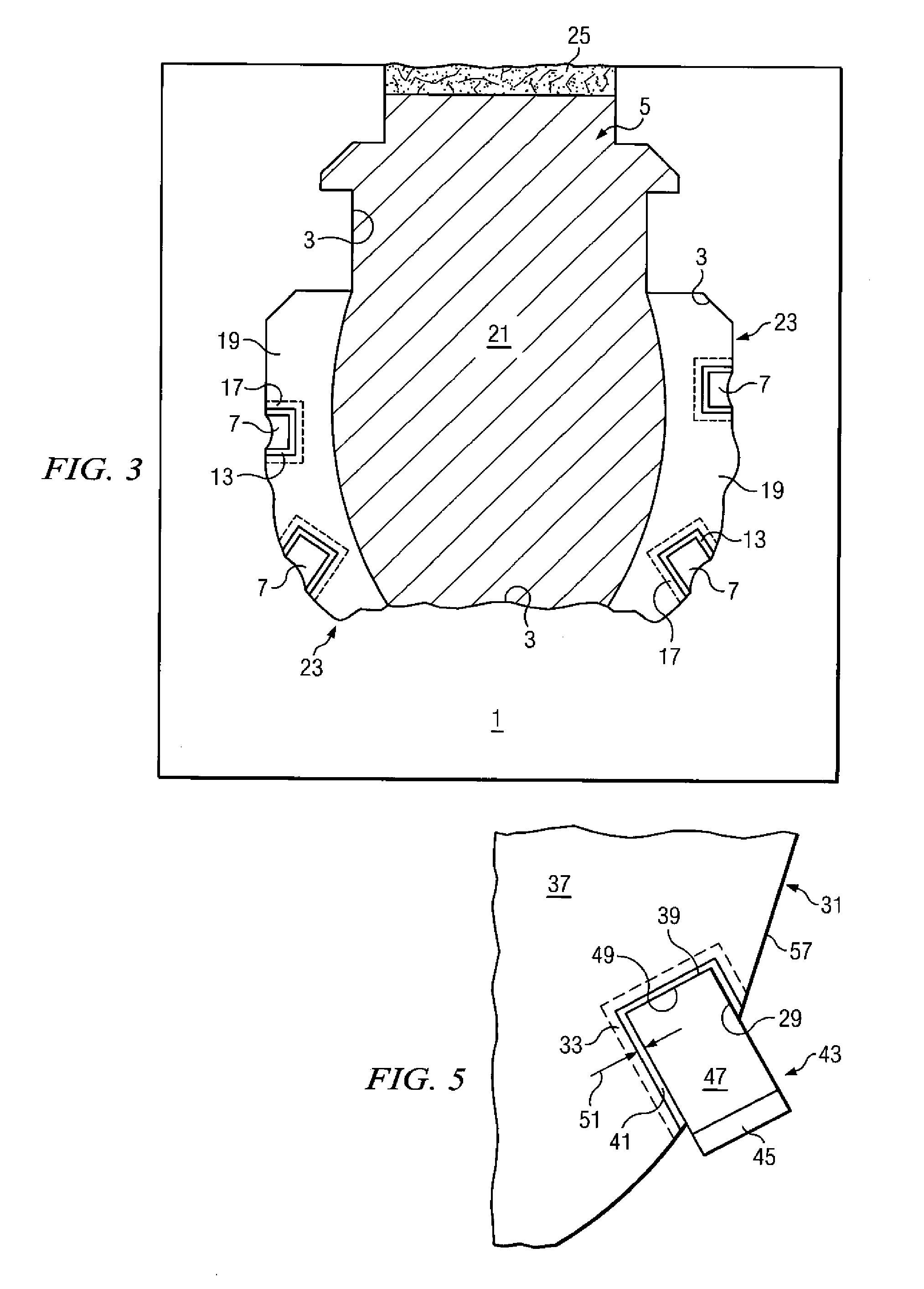
[0022]The present invention is directed to a drill bit that includes pockets, holes, indentations or other cavities for receiving any of various cutting elements or inserts, and to a method for forming the same. Hereinafter, the various cavities will be referred to collectively as pockets.

[0023]The pockets extend into the bit body and include inner surfaces formed of a material that provides improved braze strength between the pocket and a cutting element brazed to the pocket. In one exemplary embodiment, the pockets are lined with a layer of first material that is surrounded by a second material. The second material includes a higher concentration of superabrasive crystals therein, than the first material. In an exemplary embodiment, the second material includes a 5-50% weight concentration of superabrasive crystals therein, and the layer of first material that lines the pockets may include less than a 1% weight concentration of superabrasive crystals therein. The layer of first ma...


PUM

PropertyMeasurementUnit
thicknessaaaaaaaaaa
thicknessaaaaaaaaaa
thicknessaaaaaaaaaa

Abstract

A bit body formed of a mixture of matrix material and superabrasive powder and including pockets lined with superabrasive-free matrix material, and a method for forming the same, are provided. The pockets are shaped to receive cutting elements therein. The superabrasive-free matrix material enhances braze strength when a cutting element is brazed to surfaces of the pocket. The method for forming the drill bit body includes providing a mold and displacements. The displacements are coated with a mixture of superabrasive free matrix-material and an organic binder. The mold is packed with a mixture of matrix material and superabrasive powder and the arrangement heated to form a solid drill bit body. When the solid bit body is removed from the mold, pockets are formed by the displacements in the bit body and are lined with the layer of superabrasive-free matrix material. The superabrasive material may be diamond, polycrystalline cubic boron nitride, SiC or TiB2 in exemplary embodiments.

Description

CROSS-REFERENCE TO RELATED APPLICATIONS[0001]This application is a division of co-pending U.S. patent application Serial No. 10 / 455,217, filed Jun. 5, 2003 which is hereby incorporated by reference in its entirety.[0002]This application is related to co-pending U.S. patent application Ser. No. 10 / 455,281, entitled “Drill Bit Body with Multiple Binders”, filed Jun. 5, 2003, and Ser. No. 10 / 454,924, entitled “Bit Body Formed of Multiple Matrix Materials and Method for Making the Same”, filed Jun. 5, 2003, the contents of each of which are hereby incorporated by reference in their entirety.BACKGROUND OF THE INVENTION[0003]1. Field of the Invention[0004]The present invention relates, most generally, to an earth boring drill bit that includes cutting elements, and a method for forming the drill bit.[0005]2. Background of the Invention[0006]Various types of drill bits that include cutting elements are used in today=s earth drilling industries. The drill bits typically include cutting elem...

Claims


Application Information

Patent Timeline
Patent Type & Authority Applications(United States)
IPC IPC(8): E21B10/55E21B10/00E21B10/42B22F7/06B25B5/14E21B10/56E21B10/567
CPCB22F7/06E21B10/567B22F2005/001B22F7/062
Inventor IZAGUIRRE, SAUL N.OLDHAM, THOMAS W.KEMBAIYAN, KUMAR T.CHUNN, GARY R.GRIFFO, ANTHONYDENTON, ROBERTWHITE, BRIAN
Owner SMITH INT INC
Why Eureka
Try Eureka