Hydraulic Mount Having Double Idle Rate Dip Frequencies of Dynamic Stiffness

a technology of dynamic stiffness and idle rate, which is applied in the direction of machine supports, mechanical equipment, shock absorbers, etc., can solve the problems of low dynamic stiffness and damping, undesirable noise factor in idle air chamber, and difficulty in adjusting the idle ra

Inactive Publication Date: 2010-04-29
GM GLOBAL TECH OPERATIONS LLC
View PDF17 Cites 18 Cited by
  • Summary
  • Abstract
  • Description
  • Claims
  • Application Information

AI Technical Summary

Benefits of technology

[0027]According to the present invention, vibration of the upper member with respect to the lower member is transmitted to the main resilient element. With the tunable air conduit open to atmosphere, the idle inertia track is resonance tuned, in responsive combination with the resilient deformation of the main resilient element and the idle diaphragm, to provide a first idle rate dip of dynamic stiffness, and, further thereto, the tunable air conduit is resonance tuned, empirically or mathematically as for example based upon the physics of air resonance in an open tube, to provide a second idle rate dip, wherein the first and second idle rate dips are preferably selected to each coincide, respectively, with the vibration orders of the one times and two time engine firing frequencies.

Problems solved by technology

While hydraulic mounts work well, there is the problem that each of the tracks, the idle inertia track and the bounce inertia track, provide low dynamic stiffness and damping at a respective predetermined range of frequency of vibration.
The vacuum tubing interconnecting with the idle air chamber introduces an undesirable noise factor in the sense of an unwanted dynamic stiffness.
Therefore in the prior art, the existence of the vacuum tubing is considered problematic, and there is a general need to introduce countermeasures to reduce the dynamic stiffness caused by the vacuum tubing, or move the unwanted dynamic stiffness it to a frequency range which is not under consideration with respect to optimization of the idle rate dip.

Method used


Image

  • Hydraulic Mount Having Double Idle Rate Dip Frequencies of Dynamic Stiffness
  • Hydraulic Mount Having Double Idle Rate Dip Frequencies of Dynamic Stiffness
  • Hydraulic Mount Having Double Idle Rate Dip Frequencies of Dynamic Stiffness

Examples


Embodiment Construction

[0037]Referring now to the Drawing, aspects of a double idle rate dip hydraulic mount according to the present invention will be detailed.

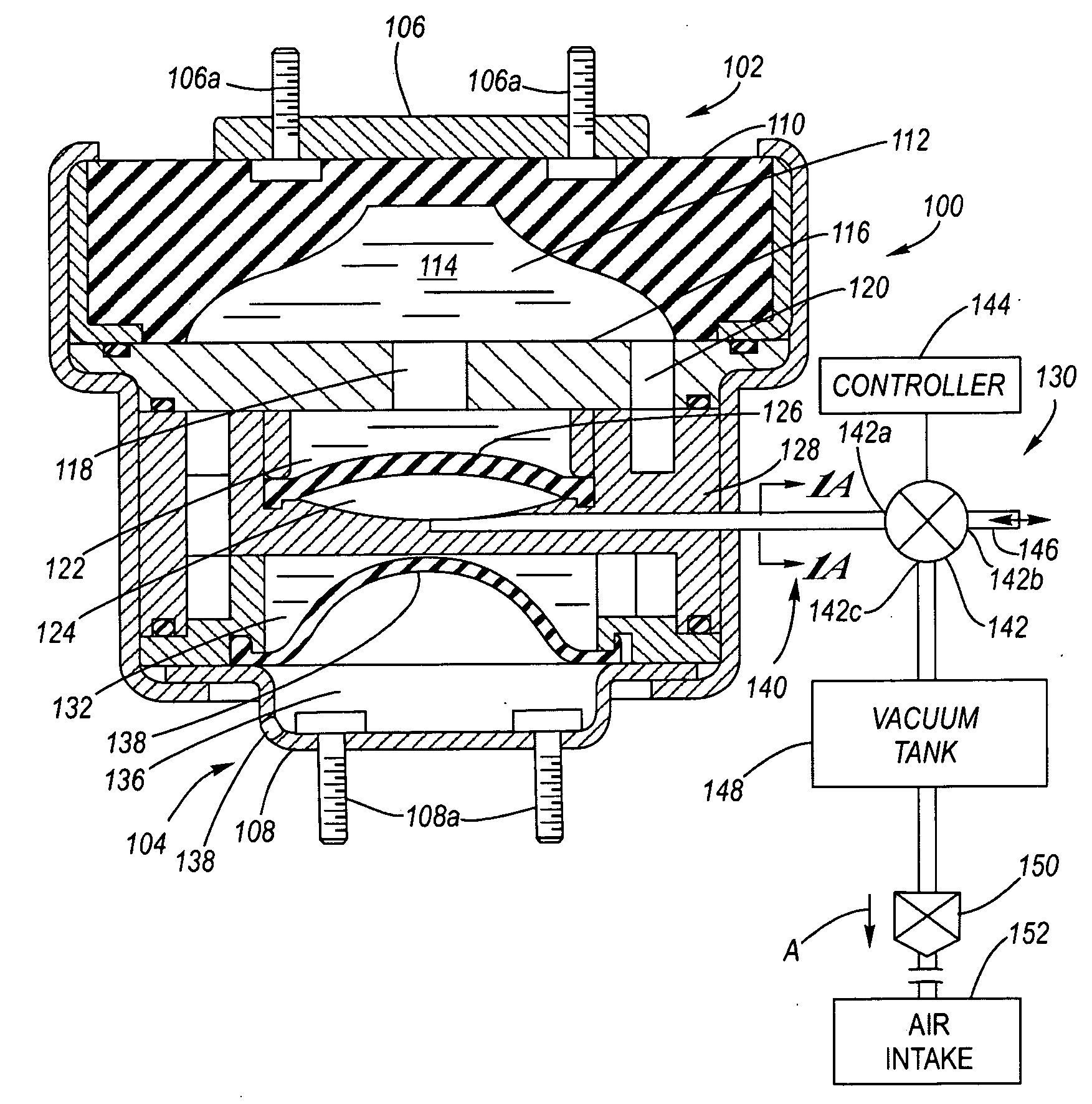
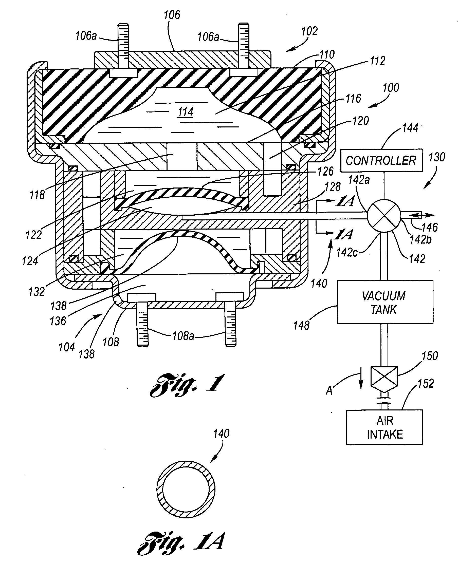
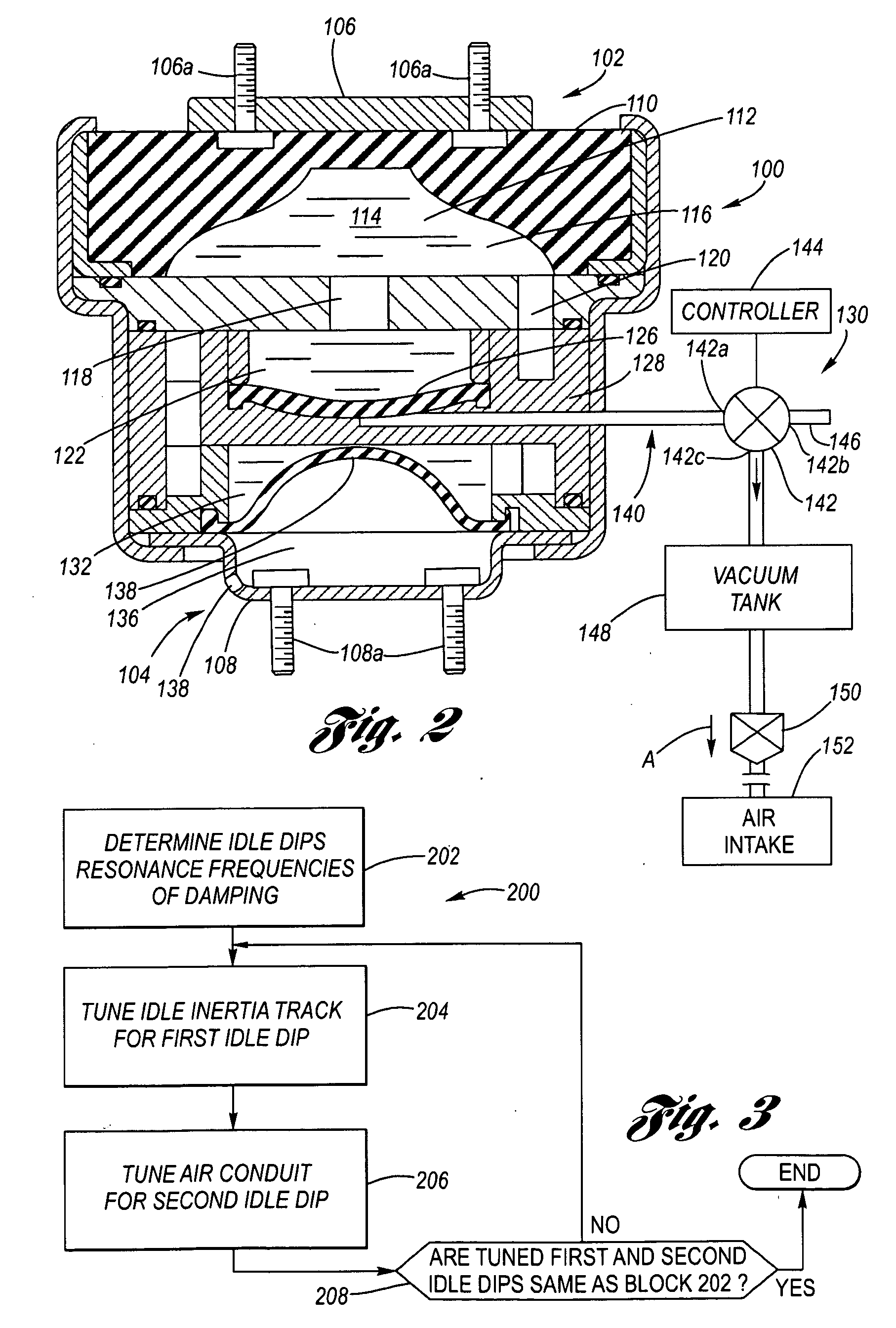
[0038]Referring firstly to FIGS. 1 through 2, an example of a double idle rate dip hydraulic mount 100 is shown, having certain structural aspects generally similar, by way of exemplification, to the disclosure of U.S. Pat. No. 5,215,293; however, it is to be understood the configuration may be other than that shown and described and that the air conduit assembly 130 as described structurally and functionally hereinbelow is unique to the present invention.

[0039]An upper member 102 resiliently interconnects with a lower member 104. The upper member 102 includes a rigid upper mounting member 106, whereby, for example, bolts 106a provide connection for example to an engine bracket (not shown). The lower member 104 includes a stamped rigid lower housing 108 whereby, for example, bolts 108a provide connection for example to the vehicle frame (not shown...


PUM


Abstract

An hydraulic mount providing double idle rate dip frequencies of dynamic stiffness, the idle rate dips being vibration orders of an internal combustion engine corresponding to one and two times firing frequencies. The double idle rate dip is achieved by providing the first idle rate dip at the first vibration order via resonance tuning of the idle inertia track, and providing the second idle rate dip at the second vibration order via additional resonance tuning of a tunable air conduit.

Description

TECHNICAL FIELD[0001]The present invention relates to hydraulic mounts, as for example used for engine mounts in motor vehicle applications, and more particularly to an hydraulic mount having a pair of idle rate dip frequencies of dynamic stiffness.BACKGROUND OF THE INVENTION[0002]Hydraulic mounts are dual aspect devices. In a first aspect, an hydraulic mount provides location of one object, such as a motor vehicle engine, with respect to a second object, as for example the frame of the motor vehicle. In a second aspect, the hydraulic mount provides damping of vibration or low dynamic stiffness as between the first and second objects, as for example damping or isolating of engine vibration with respect to the frame of the motor vehicle.[0003]Hydraulic mounts which are used for motor vehicle applications are represented, for example, by U.S. Pat. Nos. 4,828,234, 5,215,293 and 7,025,341.[0004]U.S. Pat. No. 5,215,293 discloses an hydraulic mount having a rigid upper member which is bol...

Claims


Application Information

Patent Timeline
Patent Type & Authority Applications(United States)
IPC IPC(8): F16F13/20F16F9/00F16M5/00F16F5/00F16F13/26
CPCF16F13/26
Inventor LEE, PING
Owner GM GLOBAL TECH OPERATIONS LLC
Why Eureka
Try Eureka