Night vision system

a night vision and system technology, applied in the field of night vision systems, can solve the problems of inability to use the combined scope and camera as a hands-free system, inability to move, and inability to meet the needs of mobility in the environment,

Active Publication Date: 2010-04-29
DEVCAR
View PDF29 Cites 9 Cited by
  • Summary
  • Abstract
  • Description
  • Claims
  • Application Information

AI Technical Summary

Benefits of technology

[0024]FIG. 8 shows the night vision system deployed in a remote operating condition and having a small display screen 121 coupled to one of the signal ports. In this

Problems solved by technology

There are several disadvantages realized when performing mobile surveillance with the combined devices.
Moreover, the sleeve coupling the night vision scope to the camera cannot adequately support the weight of the scope or camera.
Thus, the combined scope and camera are not for use as a hands

Method used


Image

  • Night vision system
  • Night vision system
  • Night vision system

Examples


first embodiment

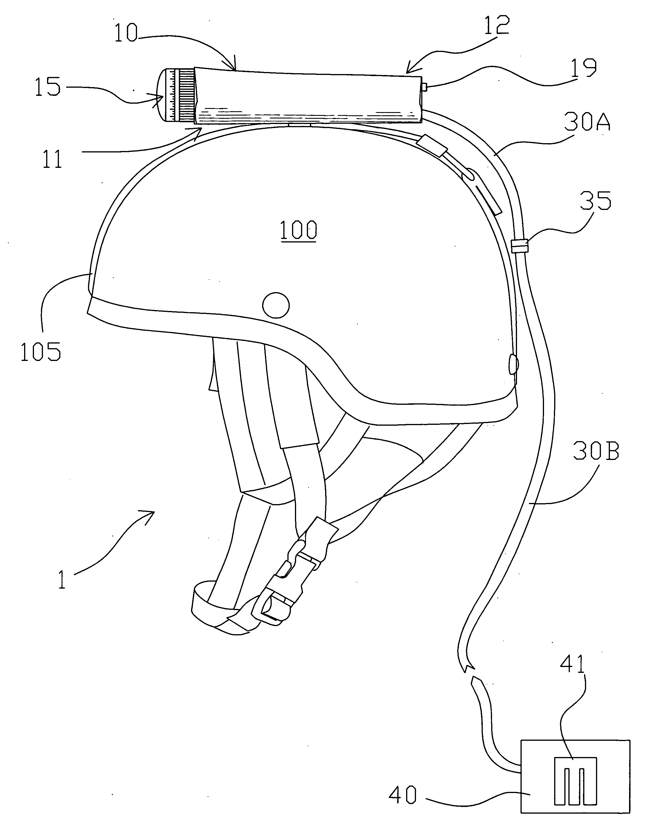
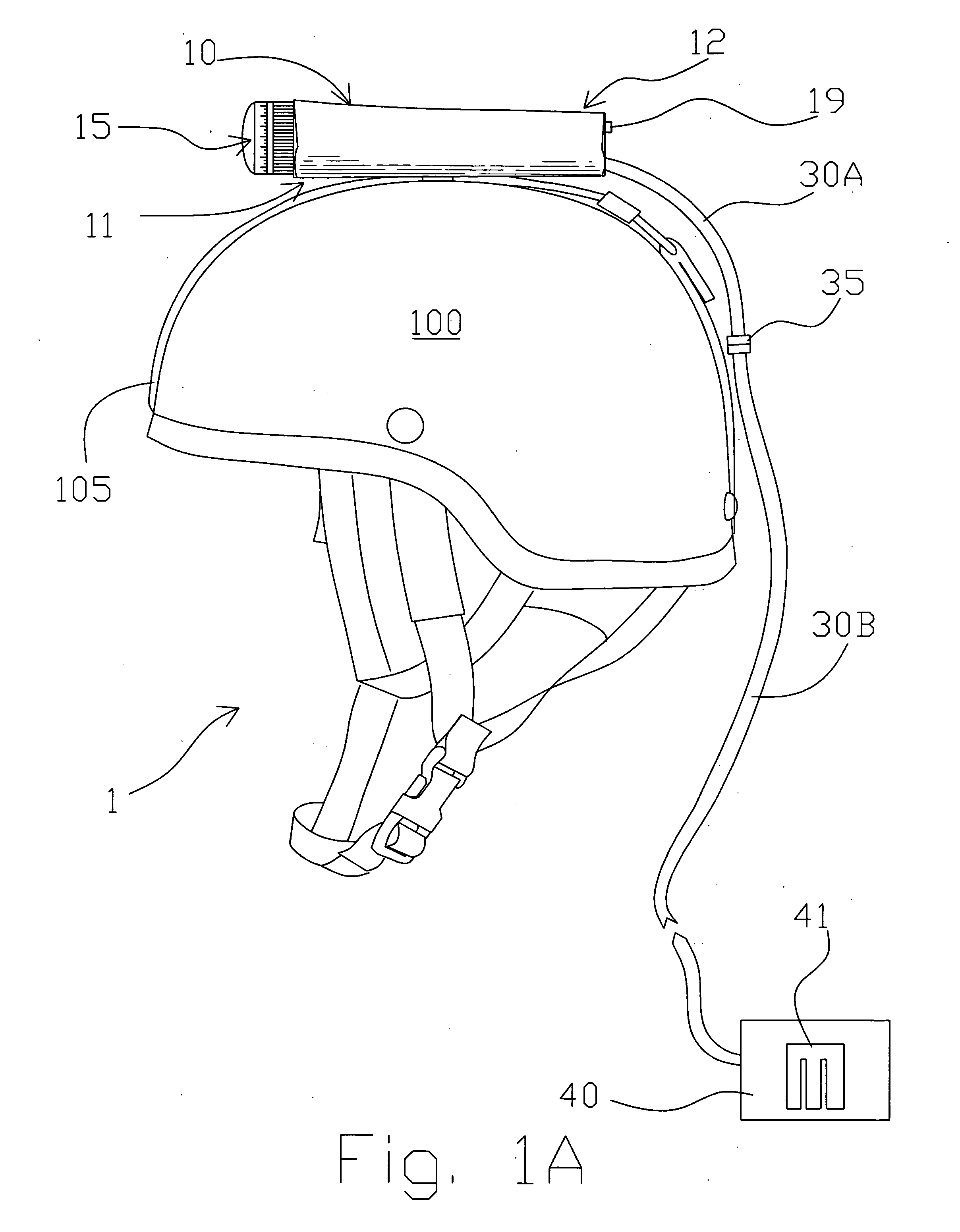
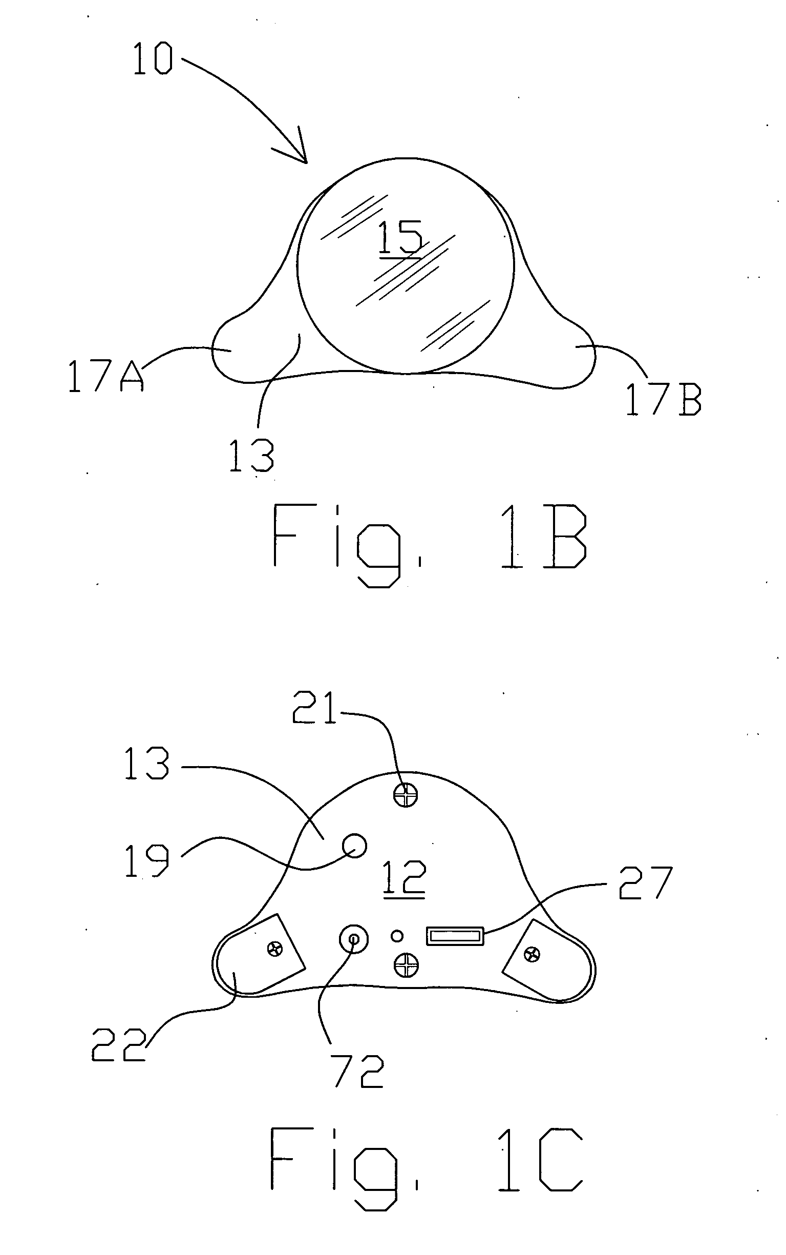
[0030]FIG. 1A shows the night vision system of the present invention 1 arranged atop a prior art helmet 100 and fastened thereto by a mounting device comprising strap 105. In a first embodiment, the image intensifier tube device 10 is preferably fastened to a strap 105 in via a strap opening formed in and arranged on a bottom of a casing 13. The image intensifier device 10 includes a front end 11 and a back end 12. An objective lens 15 is arranged at a front end of the night vision device 10 for capturing photons within the light spectrum from near infrared and visible light.

[0031]As can be understood by FIG. 3, photons 81 from a night image are passed through the objective lens 15 and into a photon to electron converter 61 such as a photocathode. The photocathode converts the photons into a first plurality of electrons 82 which are directed into a micro channel plate or electron multiplier 62 that converts the first plurality of electrons 82 into a second much larger plurality of e...

third embodiment

[0034]FIGS. 2A and 2B show two different configurations of an intensifier tube 25A, 25B. In one instance, the image intensifier tube is arranged atop the helmet 100. In an alternative embodiment, the image intensifier tube is arranged on one side of the helmet 100. In FIG. 2A, photons 81 enter the objective lens 15 and are converted into electrons via photocathode 61. An electron multiplier 62 increases the number of electrons and directs them onto screen 63 which emits photons 84 that are focused onto an image sensor 73 via lens 72. High voltage power source 65 is provided around the photocathode 61, electron multiplier 62 and screen 63. The image sensor connects to a signal conductor arranged within connector 27 to provide digital images to the memory device 40. As can be understood by viewing FIG. 2B, the photons emitted by screen 63 are directed onto the image sensor 73 via a fiber optic coupler 75 that includes a bundled, tapered plurality of fibers. FIG. 2C shows the invention...


PUM


Abstract

A night vision system includes an image intensifier tube and circuitry coupled to a digital storage medium that periodically samples a signal provided by the image intensifier tube and stores the sampled image to be viewed in near real time or at a later date by a data analyst. The night vision system includes a casing surrounding the image intensifier tube and the associated circuitry along with a port for accepting a power and/or signal cable for providing power to the image intensifier tube and image signal data to the digital storage medium. The system may further include a daytime camera and a switch for toggling the image signal data input to the digital storage medium between the daytime camera and the image intensifier tube.

Description

[0001]The present application relates to and claims priority from U.S. Provisional Patent Application Ser. No. 61 / 197,259 filed on Oct. 27, 2008.[0002]The present application did not receive any federal research and / or development funding.TECHNICAL FIELD[0003]Generally, the present invention relates to a night vision system deployed by an operator in a field environment. The system may be coupled onto the personal clothing, holsters, protective equipment or the like and used to capture images and store them onto a digital storage medium. The system includes an image intensifier device that converts night time images into digital images that may be viewed in real-time and which are stored in a data storage medium arranged on the operator or at a separate location remote from the image intensifier tube. When deployed as a helmet mounted night vision system, a pair of cables, each having a connector arranged at an end thereof, couple the image intensifier tube and the storage medium to...

Claims


Application Information

Patent Timeline
IPC IPC(8): H04N7/18
CPCG02B6/00G02B27/0176H04N7/183H04N5/2254H04N5/23241G02B2027/0138H04N23/55H04N23/65
Inventor O'ROURKE, BRIAN
Owner DEVCAR
Why Eureka
Try Eureka