Variable displacement type compressor with displacement control mechanism

a variable displacement type and compressor technology, applied in the direction of machines/engines, multi-cylinder pumps, positive displacement liquid engines, etc., can solve the problems of insufficient degree of opening of the second control valve, excessive pressure in the pressure control chamber, and long time before the displacement of the compressor is increased to the desired level, so as to reduce the degree of opening of the valve hole

Active Publication Date: 2010-04-29
TOYOTA IND CORP
View PDF6 Cites 13 Cited by
  • Summary
  • Abstract
  • Description
  • Claims
  • Application Information

AI Technical Summary

Benefits of technology

[0013]A variable displacement type compressor has a supply passage for supplying refrigerant gas to a pressure control chamber, a release passage for releasing the refrigerant gas from the pressure control chamber, a first control valve for controlling the amount of the refrigerant gas flowing through the supply passage, a check valve provided between the first control valve and the pressure control chamber and preventing the refrigerant gas from flowing from the pressure control chamber to the first control valve by closing the supply passage and a second control valve for adjusting a cross-sectional area of the release passage from minimum to maximum. The second control valve has a back pressure chamber communicating with the supply passage, a valve chamber forming a part of the release passage and communicating with a suction-pressure region, a valve hole forming a part of the release passage and communicating with the valve chamber and a spool having a valve portion located in the valve chamber. When a pressure in the back pressure chamber increases, the valve portion decreases the degree of opening of the valve hole.

Problems solved by technology

As a result, the liquefied refrigerant is vaporized in the pressure control chamber and the pressure in the pressure control chamber is increased excessively.
Therefore, it takes a long time before the displacement of the compressor is increased to a desired level after the compressor is started.
Since the liquefied refrigerant in the pressure control chamber is then stirred and the pressure in the pressure control chamber increases, the spool is urged in the direction to minimize the degree of opening of the second control valve by the pressure of the pressure control chamber, with the result that the degree of opening of the second control valve can not be maximized.
Accordingly, the liquefied refrigerant is not discharged to the suction-pressure region quickly after a start-up of the compressor and it adversely takes a long time before the displacement of the compressor is increased to a desired level.
Accordingly, the spool is urged in the direction to minimize the degree of opening of the second control valve by the pressure in the back pressure chamber, so that the second control valve is unable to maximize the degree of its opening.
Therefore, the second control valve become unable to adjust the discharge of refrigerant gas through the release passage, so that the adjustment of the swash plate to the desired inclination angle cannot be accomplished.

Method used


Image

  • Variable displacement type compressor with displacement control mechanism
  • Variable displacement type compressor with displacement control mechanism
  • Variable displacement type compressor with displacement control mechanism

Examples


first embodiment

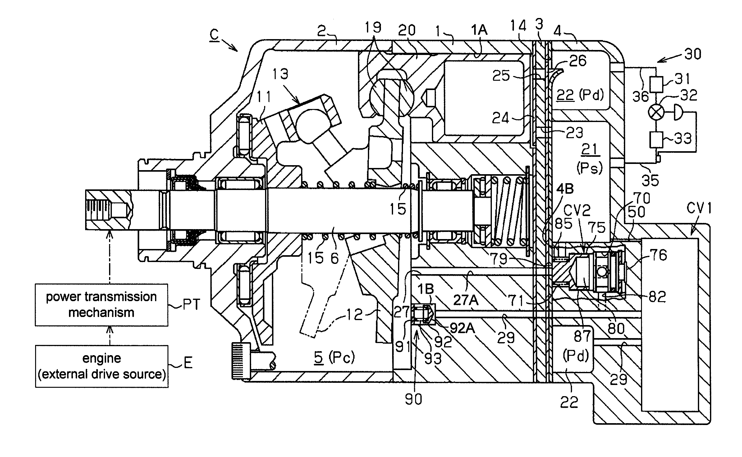
[0023]The following will describe the first embodiment of a variable displacement type compressor (hereinafter, simply referred to as compressor) with a displacement control mechanism according to the present invention, which may be used for a vehicle air conditioner to compress refrigerant gas. Referring to FIG. 1, the compressor is generally designated by C. The left side and the right side of the compressor C as viewed in FIG. 1 correspond to the front side and the rear side thereof.

[0024]As shown in FIG. 1, the compressor C has a housing including a cylinder block 1, a front housing 2 connected to the front end of the cylinder block 1 and a rear housing 4 connected to the rear end of the cylinder block 1 through a valve plate assembly 3. The cylinder block 1 and the front housing 2 cooperate to define a pressure control chamber 5 in the housing. A rotary shaft 6 is rotatably supported by the cylinder block 1 and the front housing 2. A lug plate 11 is fixed to the rotary shaft 6 ...

second embodiment

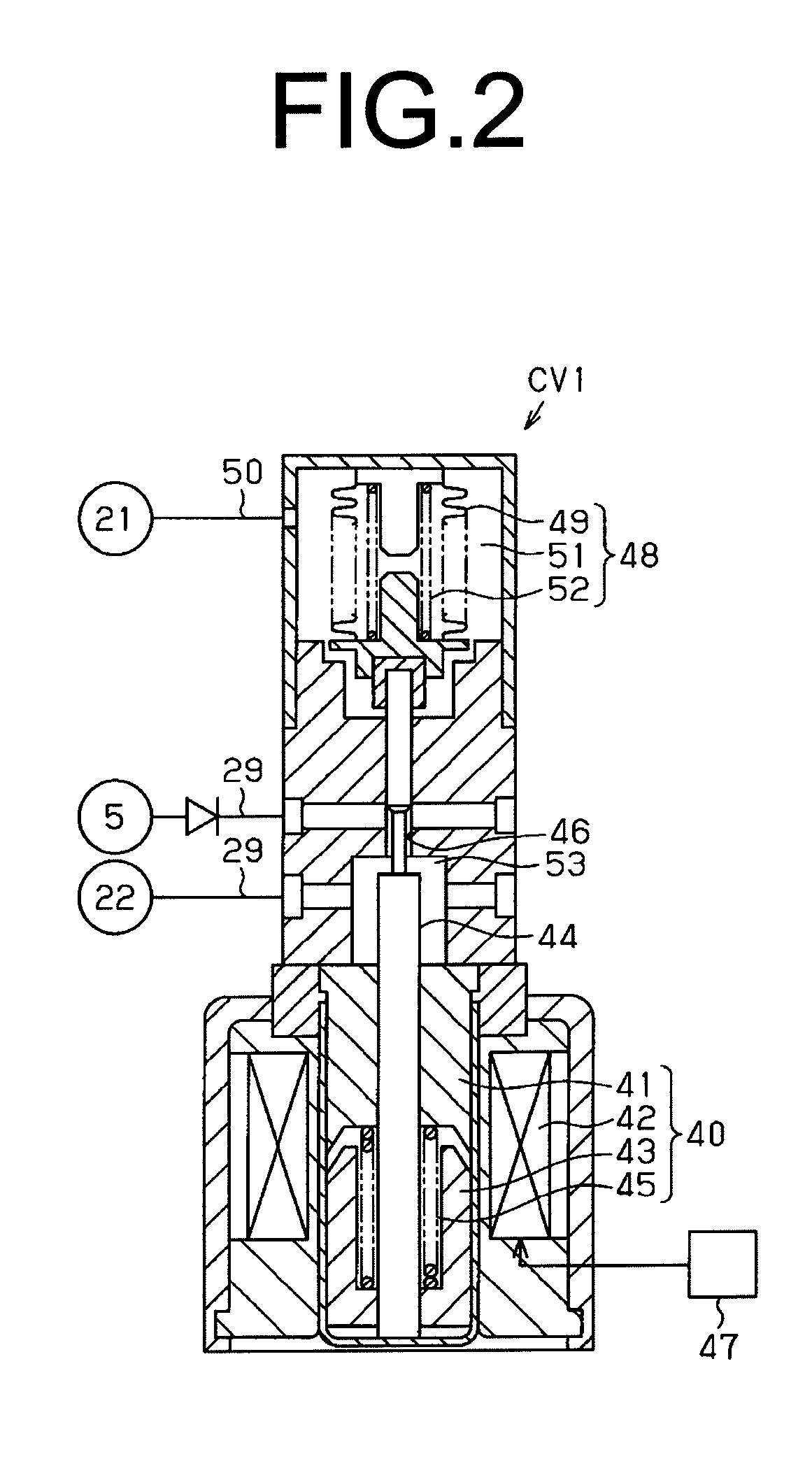
[0070]The following will describe the second embodiment of a variable displacement type compressor (hereinafter, simply referred to as compressor) with a displacement control mechanism according to the present invention, which may be used for a vehicle air conditioner to compress refrigerant gas.

[0071]Referring to FIG. 5 showing the second embodiment of compressor in an enlarged fragmentary cross-sectional view, a groove 78A is formed in the step 78 of the spool 75 of the second control valve CV2 at a position adjacent to the outer periphery of the large-diameter portion 75B of the spool 75. The groove 78A interconnects the valve chamber 71 and the back pressure chamber 80 through the clearance 87 between the outer peripheral surface of the large-diameter portion 75B and the inner surface of the middle-diameter hole 72 when the movable step 78 is seated on the stationary step 83 to minimize the degree of opening of the valve hole 27A by the spool 75. Thus, the groove 78A and the cle...

third embodiment

[0075]The following will describe the third embodiment of a variable displacement type compressor (hereinafter, simply referred to as compressor) with a displacement control mechanism according to the present invention, which may be used for a vehicle air conditioner to compress refrigerant gas.

[0076]Referring to FIG. 6 showing the third embodiment of compressor in an enlarged fragmentary cross-sectional view, the spool 75 of the second control valve CV2 has formed therethrough a passage 75C interconnecting the back pressure chamber 80 and the valve chamber 71. One end of the passage 75C is opened at the back surface 81 of the spool 75 to the back pressure chamber 80 and the other end of the passage 75C is opened at the outer peripheral surface of the small-diameter portion 75A to the valve chamber 71. Thus, refrigerant gas in the back pressure chamber 80 can be supplied to the valve chamber 71 through the passage 75C.

[0077]The compressor of the third embodiment dispenses with the s...


PUM


Abstract

A variable displacement type compressor has a supply passage for supplying refrigerant gas to a pressure control chamber, a release passage for releasing the refrigerant gas from the pressure control chamber, a first control valve for controlling the amount of the refrigerant gas flowing through the supply passage, a check valve provided between the first control valve and the pressure control chamber and preventing the refrigerant gas from flowing from the pressure control chamber to the first control valve by closing the supply passage and a second control valve for adjusting a cross-sectional area of the release passage from minimum to maximum. The second control valve has a back pressure chamber communicating with the supply passage, a valve chamber forming a part of the release passage and communicating with a suction-pressure region, a valve hole forming a part of the release passage and communicating with the valve chamber and a spool having a valve portion located in the valve chamber. When a pressure in the back pressure chamber increases, the valve portion decreases the degree of opening of the valve hole.

Description

BACKGROUND OF THE INVENTION[0001]The present invention relates to a displacement control mechanism for a variable displacement type compressor which is operable to adjust the pressure in a pressure control chamber by supplying refrigerant gas in a discharge-pressure region of the compressor into the pressure control chamber and releasing the refrigerant gas in the pressure control chamber to a suction-pressure region of the compressor, thereby controlling the displacement of the compressor.[0002]In a variable displacement type compressor provided with a pressure control chamber having therein a swash plate whose inclination angle is variable, the inclination angle of the swash plate decreases with an increase of the pressure in the pressure control chamber. On the other hand, the inclination angle of the swash plate increases with a decrease of the pressure in the pressure control chamber. When the inclination angle of the swash plate decreases, the stroke of a piston decreases ther...

Claims


Application Information

Patent Timeline
Patent Type & Authority Applications(United States)
IPC IPC(8): F04B1/26F04B1/12
CPCF04B27/1804F04B2027/1827F04B2027/1872F04B2027/1859F04B2027/1881F04B2027/1854F04B25/04F04B27/08
Inventor OTA, MASAKIKUBO, HIROSHIMATSUBARA, RYOTABE, YASUHIROYAMASHITA, HIDEHARUMORIKAGE, YUKI
Owner TOYOTA IND CORP
Why Eureka
Try Eureka