Refrigeration apparatus

a refrigerant and compressor technology, applied in the field of refrigerating apparatus, can solve the problems of degrading cooling performance, reduce the specific enthalpy of refrigerant at the inlet side of the main diaphragm means of the showcase, reduce the amount of compressor rotation, and increase the cooling effect

Inactive Publication Date: 2017-09-28
PANASONIC INTELLECTUAL PROPERTY MANAGEMENT CO LTD
View PDF7 Cites 0 Cited by
  • Summary
  • Abstract
  • Description
  • Claims
  • Application Information

AI Technical Summary

Benefits of technology

[0010]Thereby, in the intermediate cooler, gas-liquid separation is performed and thereby the refrigerant is liquefied. As a result, the refrigerator outlet pressure is made less than the critical pressure, so that a liquid refrigerant can be sent to the showcase. Thereby, the specific enthalpy of the refrigerant at the inlet side of the main diaphragm means of the showcase can be reduced, and the cooling effect can be increased.
[0011]In the above-described configuration, when the difference between the high pressure at the discharge side of the compressor and the design pressure is less than 1 MPa, the control apparatus performs control to reduce the amount of rotation of the compressor.
[0012]In the above-described configuration, the control apparatus may also perform control such that, when the difference between the high pressure at the discharge side of the compressor and the design pressure is less than 1 MPa, the amount of rotation of the compressor is reduced, and such that, after the difference between the high pressure at the discharge side of the compressor and the design pressure is secured, the opening degree of the decompression electric valve is reduced.
[0013]According to the present invention, the refrigerator outlet pressure can be less than the critical pressure, and the liquid refrigerant can be sent to the showcase. Thereby, the specific enthalpy of the refrigerant at the inlet side of the main diaphragm means of the showcase can be reduced, and the cooling effect can be increased.

Problems solved by technology

In this case, there is a problem that, since the refrigerant cannot be liquefied in the intermediate cooler, the cooling effect cannot be improved by liquefaction, and hence, the cooling performance is degraded.

Method used


Image

  • Refrigeration apparatus
  • Refrigeration apparatus
  • Refrigeration apparatus

Examples


Embodiment Construction

)

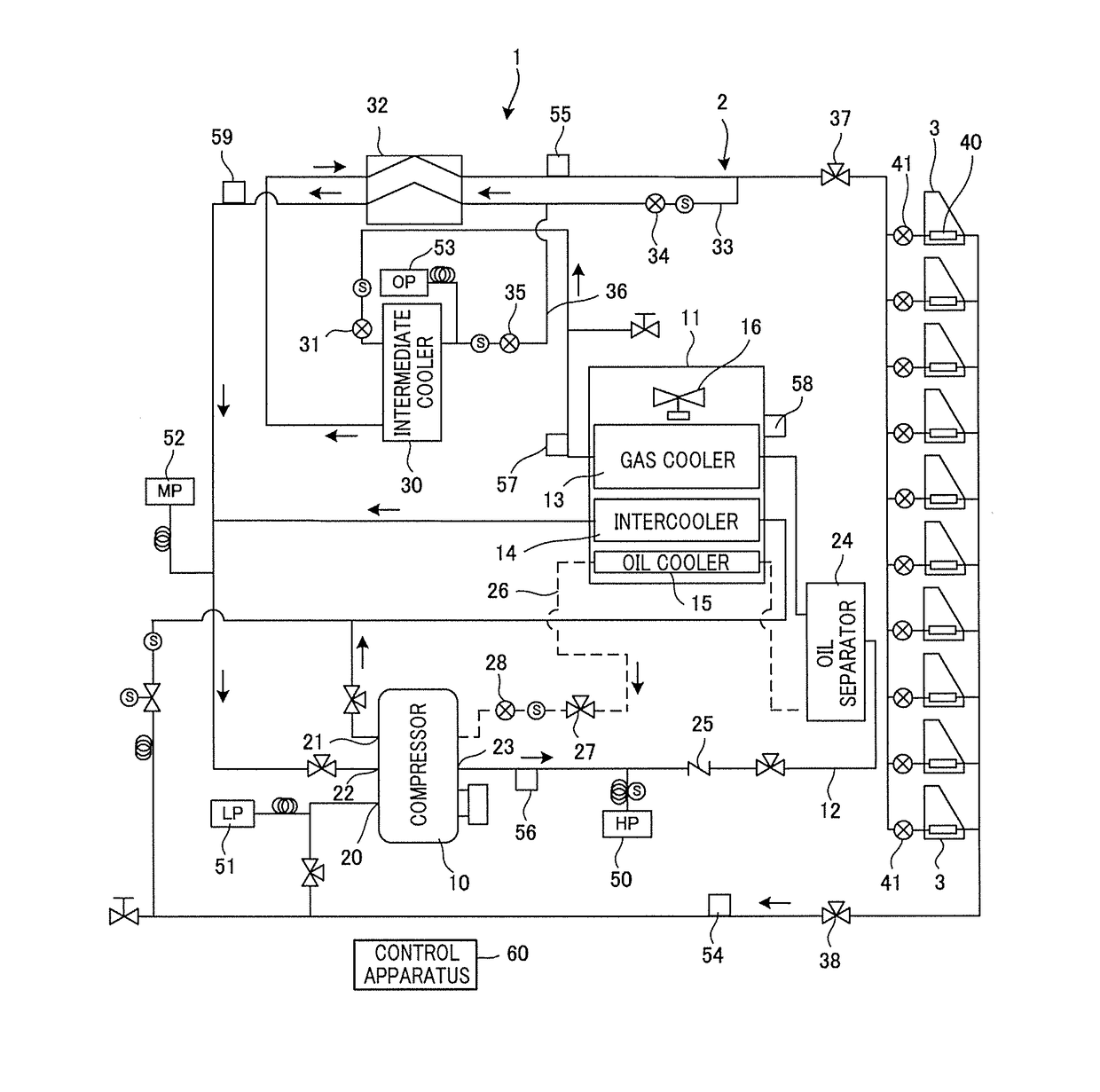
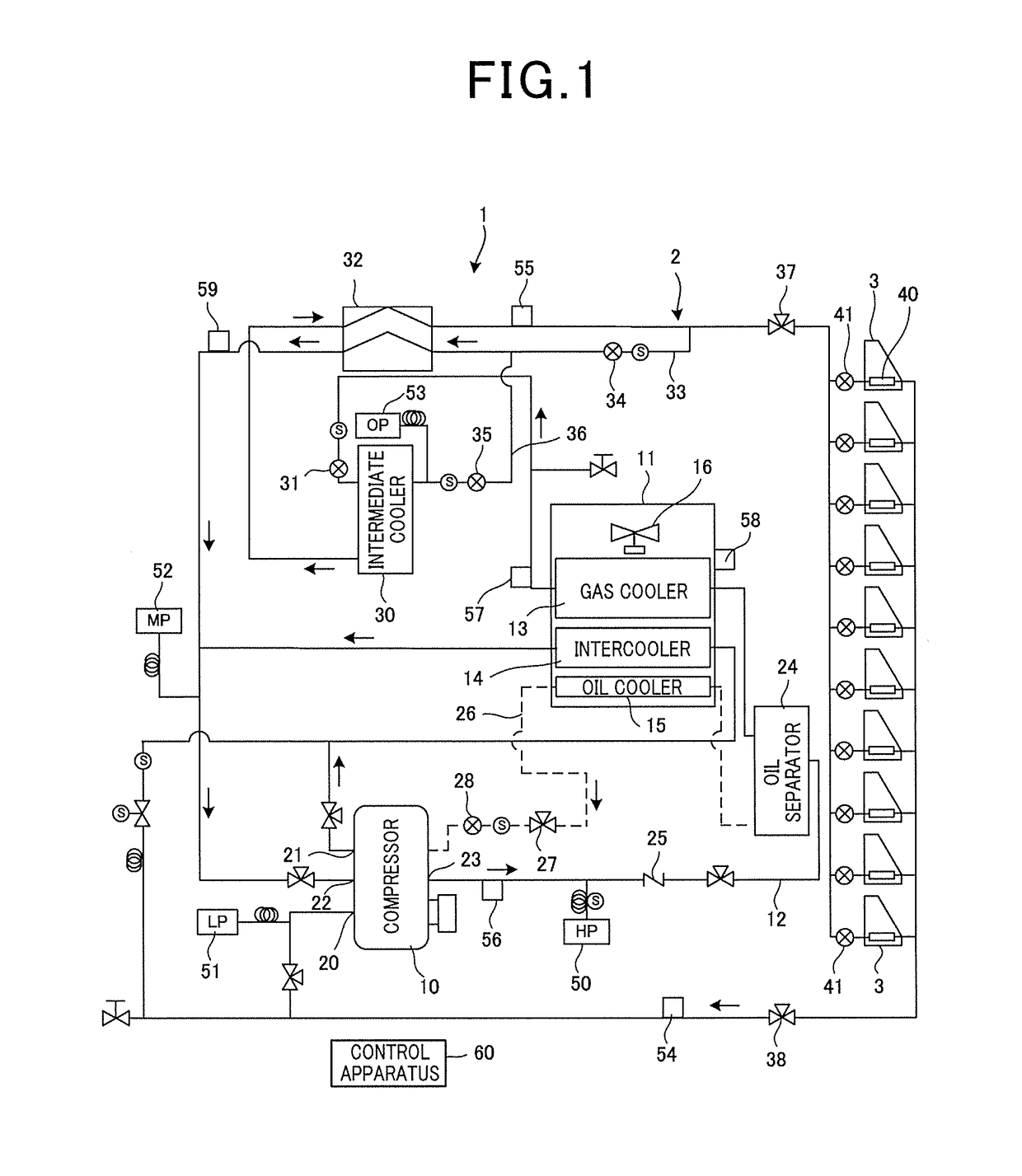
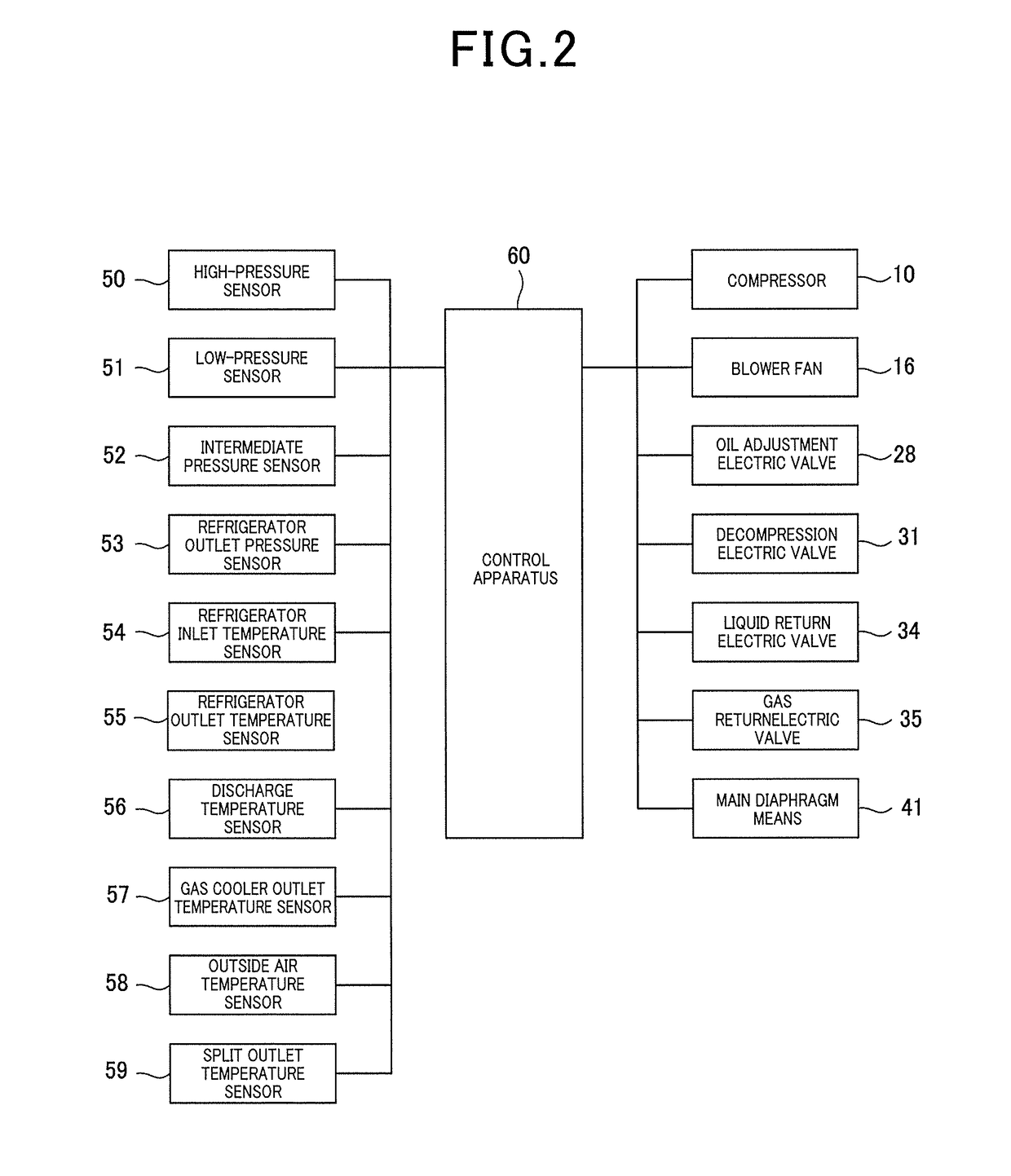
[0018]A first invention provides a refrigeration apparatus which includes: a refrigerator having a two-stage compression compressor, an intercooler, a gas cooler, a decompression electric valve, an intermediate cooler, and a gas return electric valve; and a showcase having main diaphragm means and a evaporator, the refrigeration apparatus being characterized by including a control apparatus which performs control to reduce the opening degree of the decompression electric valve at the upstream side of the intermediate cooler when the outlet pressure at the refrigerator is higher than the critical pressure.

[0019]Thereby, in the intermediate cooler, the refrigerator outlet pressure can be made lower than the critical pressure, and hence, the refrigerant is separated into a gas refrigerant and a liquid refrigerant, so that the liquid refrigerant is sent to the showcase. Thereby, at the inlet side of the main diaphragm means of the showcase, the specific enthalpy of the refrigerant can ...


PUM


Abstract

Provided is a refrigeration apparatus which can reduce outlet pressure of a refrigerator even in overload conditions and which can improve refrigeration capacity by liquefying a refrigerant in an intermediate cooler. When outlet pressure of a refrigerator 2 is higher than critical pressure, a control apparatus 60 performs control to reduce the opening degree of a decompression electric valve 31 at the upstream side of an intermediate cooler 30. Thereby, the refrigerant is liquefied by gas-liquid separation in the intermediate cooler 30, so that the refrigerator outlet pressure is made less than the critical pressure, and the liquid refrigerant can be sent to a showcase 3. As a result, the specific enthalpy of the refrigerant at the inlet side of main diaphragm means 41 of the showcase 3 can be reduced, and thereby, the cooling effect can be increased.

Description

INCORPORATION BY REFERENCE[0001]The present application claims priority under 35 U.S.C.§119 to Japanese Patent Application No. 2016-061616 filed on Mar. 25, 2016. The content of the application is incorporated herein by reference in its entirety.BACKGROUND OF THE INVENTION[0002]Field of the Invention[0003]The present invention is relates to a refrigeration apparatus, and more particularly to a refrigeration apparatus in which a refrigerant circuit is configured by a compressor, a gas cooler, an intermediate heat exchanger, and an evaporator, and in which the high pressure side is set to supercritical pressure.[0004]Description of the Related Art[0005]Conventionally, for example, in a large store, such as a supermarket, many refrigeration showcases and many cold storage showcases are installed. In the showcase, a refrigeration apparatus which operates a refrigerator is used in many cases.[0006]Conventionally, in the refrigeration apparatus, for example, a technique is disclosed, in w...

Claims


Application Information

Patent Timeline
Patent Type & Authority Applications(United States)
IPC IPC(8): F25B49/02F25B41/04F25B13/00F25B41/31
CPCF25B49/02F25B2600/2513F25B41/04F25B13/00F25B1/10F25B49/022F25D13/00F25B41/39F25B41/20F25B2400/23F25B9/008F25B2600/0271F25B2700/2109F25B2309/061F25B2400/072F25B2700/21152F25B2400/13F25B2700/21151F25B2700/2106F25B5/02F25B2600/0253F25B2700/1933F25B2700/21163F25B2700/1931Y02B30/70
Inventor KURATA, YUSUKEMIHARA, KAZUHIKOIZAWA, YUICHIKUWABARA, OSAMU
Owner PANASONIC INTELLECTUAL PROPERTY MANAGEMENT CO LTD
Why Eureka
Try Eureka