
Apparatus for treating venous insufficiency

a technology for varicose veins and apparatuses, applied in medical science, surgery, therapeutic cooling, etc., can solve the problems of inability to close the valve, increase the strain and pressure on the lower venous sections and overlying tissues, and achieve the effect of restoring valvular competency, less invasive, and terminating the emission of energy

Inactive Publication Date: 2010-04-29
COVIDIEN LP
View PDF8 Cites 9 Cited by
  • Summary
  • Abstract
  • Description
  • Claims
  • Application Information

AI Technical Summary

Benefits of technology

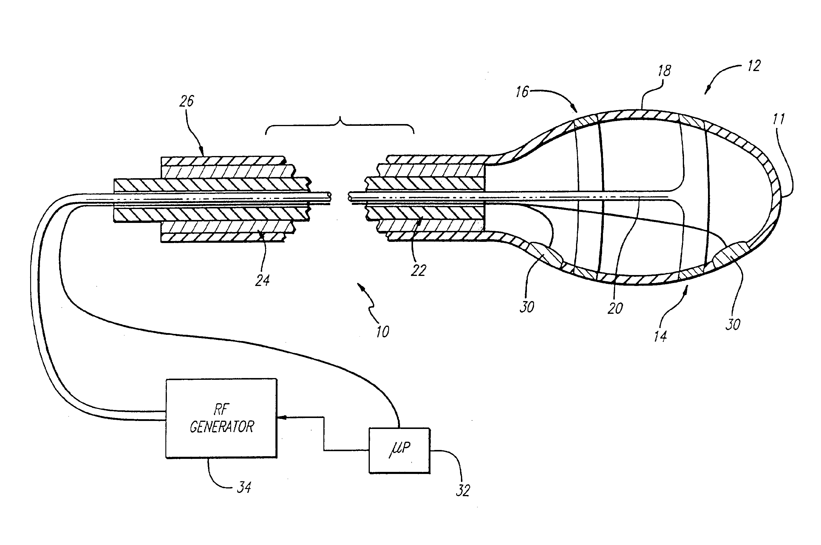
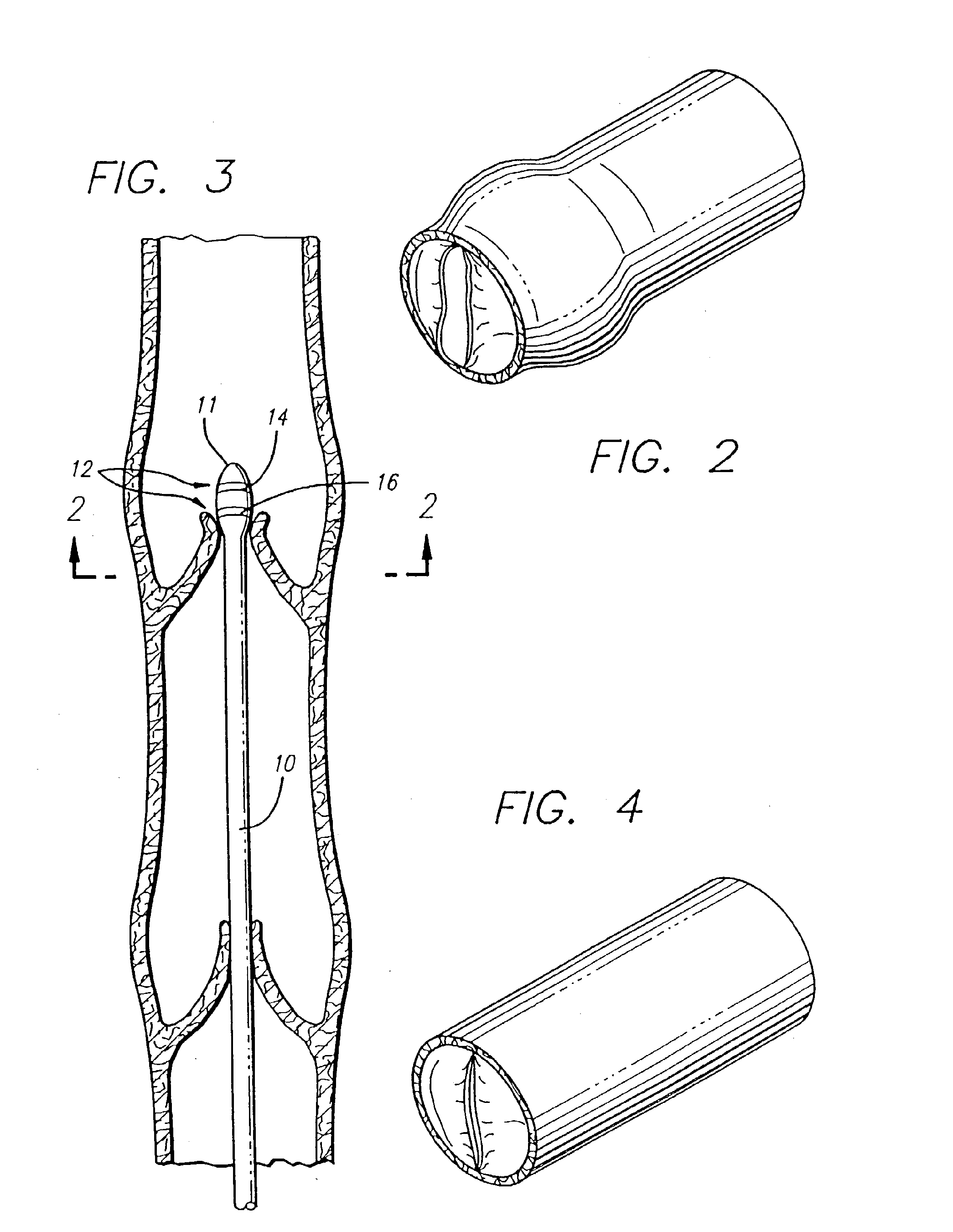
[0012]Briefly, and in general terms, the present invention provides a less invasive and faster method for solving the underlying problems of varicose veins and venous insufficiency, and uses a novel repair system, including a catheter for placement of an electrode for delivering radio frequency energy. The present invention includes a method of applying energy to cause shrinkage of a vein, the method comprising the steps of introducing a catheter having a working end and means for heating located at the working end, to a treatment site in a vein; positioning the means for heating at the treatment site in the vein; applying energy from the means for heating to controllably heat the treatment site and cause shrinkage of the vein; and terminating the emission of energy from the means for heating after sufficient shrinkage of the vein has occurred so as to restore valvular competency or so that the vein remains patent so as to continue to function as a blood conduit.
[0013]The method of the present invention is a minimally invasive procedure which eliminates the need for open surgical procedures for venous repair, including venous valvuloplasty, and the transplantation of an arm vein into the leg.
[0014]An apparatus for performing the method of applying radiant energy to cause shrinkage of a vein, comprises a catheter having a working end, means for heating a venous treatment area to cause shrinkage of the vein, wherein the means for heating is located at the working end of the catheter, and means for preventing further shrinkage after sufficient shrinkage of the vein, so that the vein continues to function. The heating means may include RF electrodes to heat and shrink the vein. Balloons, or other mechanisms for controlling the outer diameter of the heating means, may be used to limit the amount of shrinkage. Feedback control systems may be applied to these mechanisms, or may be used to control the application of energy to heat the venous tissue, in order to control the amount of shrinkage.

Problems solved by technology

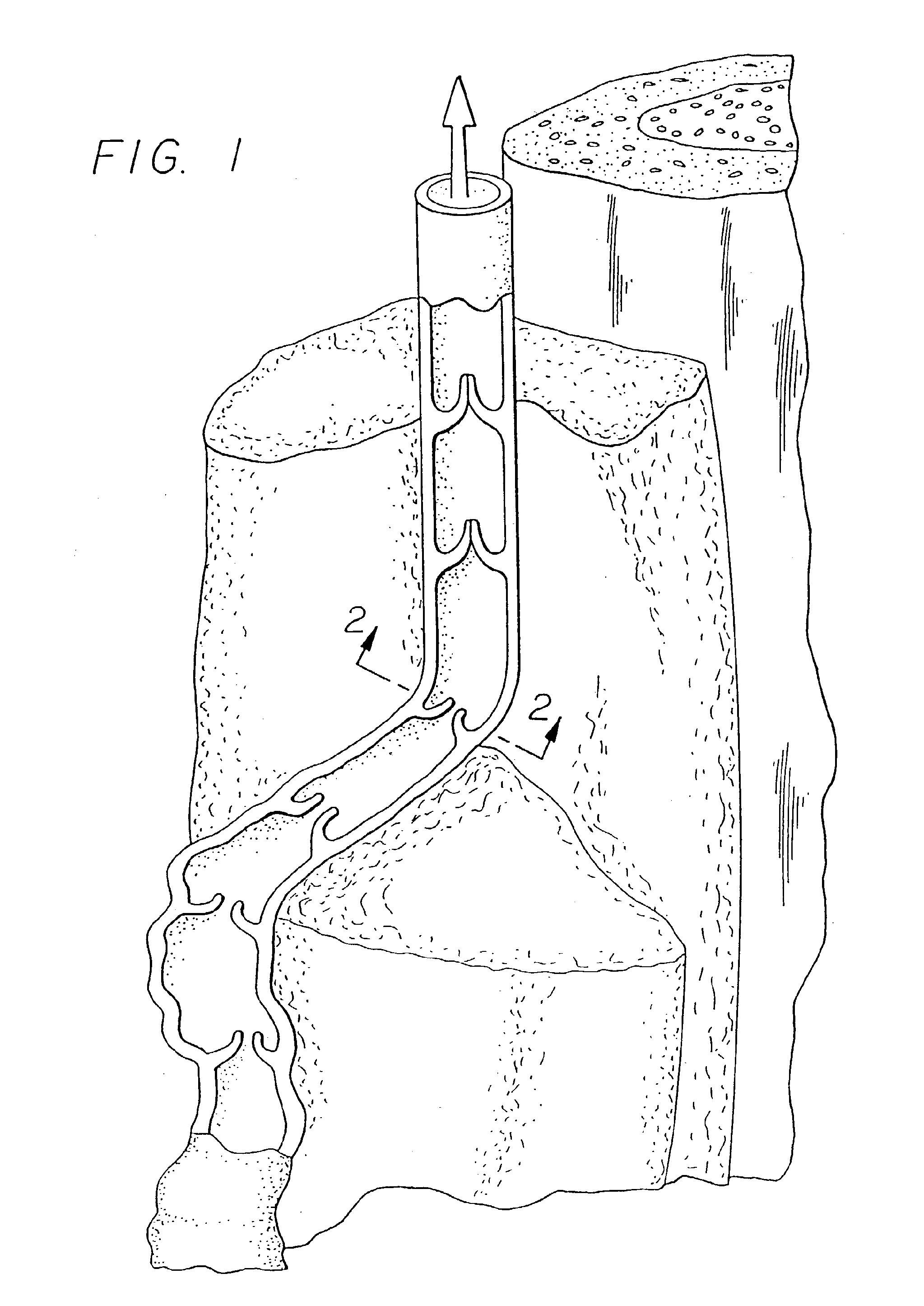
When an incompetent valve is in the flow path of retrograde flow toward the foot, the valve is unable to close because the cusps do not form a proper seal and retrograde flow of blood cannot be stopped.
Incompetence in the venous system can result from vein dilation, which causes the veins to swell with additional blood.
Stretching of the leaflets of the venous valve results in redundancy which allows the leaflets to fold on themselves and leave the valve open.
Eventually the venous valve fails, thereby increasing the strain and pressure on the lower venous sections and overlying tissues.
The varicose vein condition includes dilatation and tortuosity of the superficial veins of the lower limb, resulting in unsightly discoloration, pain and ulceration.
The removal of varicose veins from the body can be a tedious, time-consuming procedure having a painful and slow healing process.
Complications, scarring, and the loss of the vein for future cardiac and other by-pass procedures may also result.
Along with the complications and risks of invasive open surgery, varicose veins may persist or reoccur, particularly when the valvular problem is not corrected.
Due to the long, arduous, and tedious nature of the surgical procedure, treating multiple venous sections can exceed the physical stamina of the physician, and thus render complete treatment of the varicose vein conditions impractical.
Chronic venous insufficiency (CVI) is a problem caused by hydrodynamic forces acting on the tissues of the body, especially the legs, ankles and feet.
As the veins dilate due to increased pressure, the valves in the veins fail.
This causes the pressure to increase on the next valve and vein segment down, causing those veins to dilate, and as this continues, the valves in the veins eventually all fail.
As they fail, the effective height of the column of blood above the feet and ankles grows, and the weight and hydrostatic pressure exerted on the tissues of the ankle and foot increases.
When the weight of that column reaches a critical point from the valve failures, ulcerations of the ankle begin to form, which start deep and eventually come to the surface.
These ulcerations do not heal easily because the weight of blood which caused them continues to persist, and have the tendency to enlarge the ulcer.
Chronic venous insufficiency often consists of hypertension of the lower limb in the deep, perforating and often superficial veins, and may result in discoloration, pain, swelling and ulceration.
Existing treatments for chronic venous insufficiency are often less than ideal.
Moreover, invasive surgery has its associated complications with risk to life and expense.
Due to the time-consuming and invasive nature of the current surgical treatments, such as vein grafting, typically only one valve is treated during any single procedure.
This greatly limits the ability of the physician to fully treat patients suffering from chronic venous insufficiency.
Every instance of invasive surgery, however, has its associated complications with risk to life and expense.
However, ligation procedures close off the lumen, essentially destroying their functional capability.
For example, ligating the saphenous vein would render that vein unavailable for harvesting in other surgical procedures such as coronary by-pass operations.
Ligation techniques which functionally destroy the vein lumen would appear to be inappropriate to a corrective procedure for restoring and maintaining the function of the vein.

Method used


Image

  • Apparatus for treating venous insufficiency
  • Apparatus for treating venous insufficiency
  • Apparatus for treating venous insufficiency

Examples


Embodiment Construction

[0051]As shown in the exemplary drawings, the invention is directed toward the intravenous treatment of veins using a catheter to deliver at least one electrode to a venous treatment site. As used herein, like reference numerals will designate similar elements in the various embodiments of the present invention to be discussed. In addition, unless otherwise noted, the term working end will refer to the direction toward the treatment site in the patient, and the term connecting end will refer to the direction away from the treatment site in the patient. The invention will be described in relation to the treatment of the venous system of the lower limbs. It is to be understood, however, that the invention is not limited thereto and may be employed intraluminally to treat veins in other areas of the body such as hemorrhoids, esophageal varices, and venous-drainage-impotence of the penis. Furthermore, although the invention will be described as using RF energy from the electrode, it is ...


PUM


Abstract

A catheter delivers an electrode within a vein for a minimally invasive treatment of varicose veins and venous insufficiency using RF energy. The catheter is introduced into a patient and positioned within the section of the vein to be treated. The electrode radiates high frequency energy towards the vein, and the surrounding venous tissue becomes heated and begins to shrink. The catheter includes a controllable member for limiting the amount of shrinkage of the vein to the diameter of the member. The electrode remains active until there has been sufficient shrinkage of the vein. The extent of shrinkage of the vein may be detected by fluoroscopy. After treating one section of the vein, the catheter and the electrode can be repositioned intraluminally within the vein to treat different sections of the vein until all desired venous sections and valves are repaired and rendered functionally competent.

Description

CROSS-REFERENCE TO RELATED APPLICATIONS[0001]This application is a continuation of application Ser. No. 10 / 396,672, filed Mar. 25, 2003, which is a continuation of application Ser. No. 09 / 495,667, filed Feb. 1, 2000, now U.S. Pat. No. 6,613,045, which is a continuation of application Ser. No. 08 / 610,911, filed Mar. 5, 1996, now U.S. Pat. No. 6,036,687. The entire disclosures of the prior applications are hereby incorporated by reference.BACKGROUND OF THE INVENTION[0002]This invention relates to the treatment and correction of venous insufficiency or varicose veins, and more particularly to a minimally invasive procedure using a catheter-based system to deploy an electrode for providing radio frequency (RF) energy, microwave energy, or thermal energy to shrink a vein intraluminally to change the fluid flow dynamics and to restore the competency of the venous valve and the proper function of the vein.[0003]The human venous system of the lower limb consists essentially of the superfici...

Claims


Application Information

Patent Timeline
Patent Type & Authority Applications(United States)
IPC IPC(8): A61B18/14A61B17/22A61B18/08
CPCA61B18/08A61B2018/1497A61B2017/22051A61B2017/22097A61B2018/00083A61B2018/00214A61B2018/0022A61B2018/00267A61B2018/00285A61B2018/00404A61B2018/00488A61B2018/00755A61B2018/00797A61B2018/00875A61B2018/1253A61B2018/126A61B2018/1465A61B18/1492
Inventor LAUFER, MICHAEL D.FARLEY, BRIAN E.SCHULZ, GRACE Y.ZIKORUS, ARTHUR W.PARKER, MARK P.
Owner COVIDIEN LP
Learn More