Position-sensorless control system and method of operation for a synchronous motor

a synchronous motor and position sensor technology, applied in the direction of motor/generator/converter stopper, dynamo-electric converter control, dynamo-electric gear control, etc., can solve the problems of low reliability, computational complexity, and difficulty in finding feedback devices or sensors for such high operating speeds,

Inactive Publication Date: 2010-05-06
R & D DYNAMICS
View PDF8 Cites 48 Cited by
  • Summary
  • Abstract
  • Description
  • Claims
  • Application Information

AI Technical Summary

Benefits of technology

[0009]In one aspect of the present invention, a control system for an electric motor including a stator and a rotor comprises an inverter for providing power to the motor, and a controller for controlling the inverter. The inverter is controlled by the control system of the present invention via transmission of control commands for operation of the motor. The controller comprises a sensorless block, an estimated angle error detector block, a field-weakening block, and a torque-to-current converter block. The sensorless block estimates the angular position and velocity of the motor rotor and generates an estimated rotor angular position feedback signal and an estimated rotor angular velocity feedback signal. The estimated angle error detector block detects the difference between the estimated rotor angular position and a real rotor angular position, wherein the detected angular position difference is used by the sensorless block to estimate the estimated rotor angular position. The field-weakening block uses the estimated rotor angular velocity feedback signal from the sensorless block to command direct axis current and generate a torque feedback signal. The torque-to-current converter block uses the torque feedback signal generated by the field-weakening block to derive a torque current component for the motor control command. The estimated rotor angular position feedback signal is also used to generate the motor control command.
[0010]The control system of the present invention may be used in a power train for a blower/compressor system. The power train comprises an electric motor functionally coupled to the impeller of the blower/compressor system, an inverter for providing power to the motor, and a controller for controlling the inverter. The controller comprises an estimated angle error detector block and a sensorless block. The sensorless block estimates the angular position and velocity of the motor rotor. The estimated angle error detector block detects the difference between the estimated rotor angular position and the real rotor angular position, and the controller generates a command transmitted to the inverter for operation of the motor based, in part, on the estimated angular position and velocity and the detected angular position difference. The controller can also include a field-w

Problems solved by technology

Such a control system, however, is computationally intensive.
It is very difficult to find feedback devices or sensors for such high operating speeds.
Sensors that currently exist for such high speed turbo machines tend to be expensive and have low reliability.
In addition, existing position sensors often limit system configuration options.
These factors become prohibitive in high volume applications, such as for control systems used in industrial turbo-blowers and turbo-compressors.
However, existing methods are limited in various abilities.
For example, some common

Method used


Image

  • Position-sensorless control system and method of operation for a synchronous motor
  • Position-sensorless control system and method of operation for a synchronous motor
  • Position-sensorless control system and method of operation for a synchronous motor

Examples


Embodiment Construction

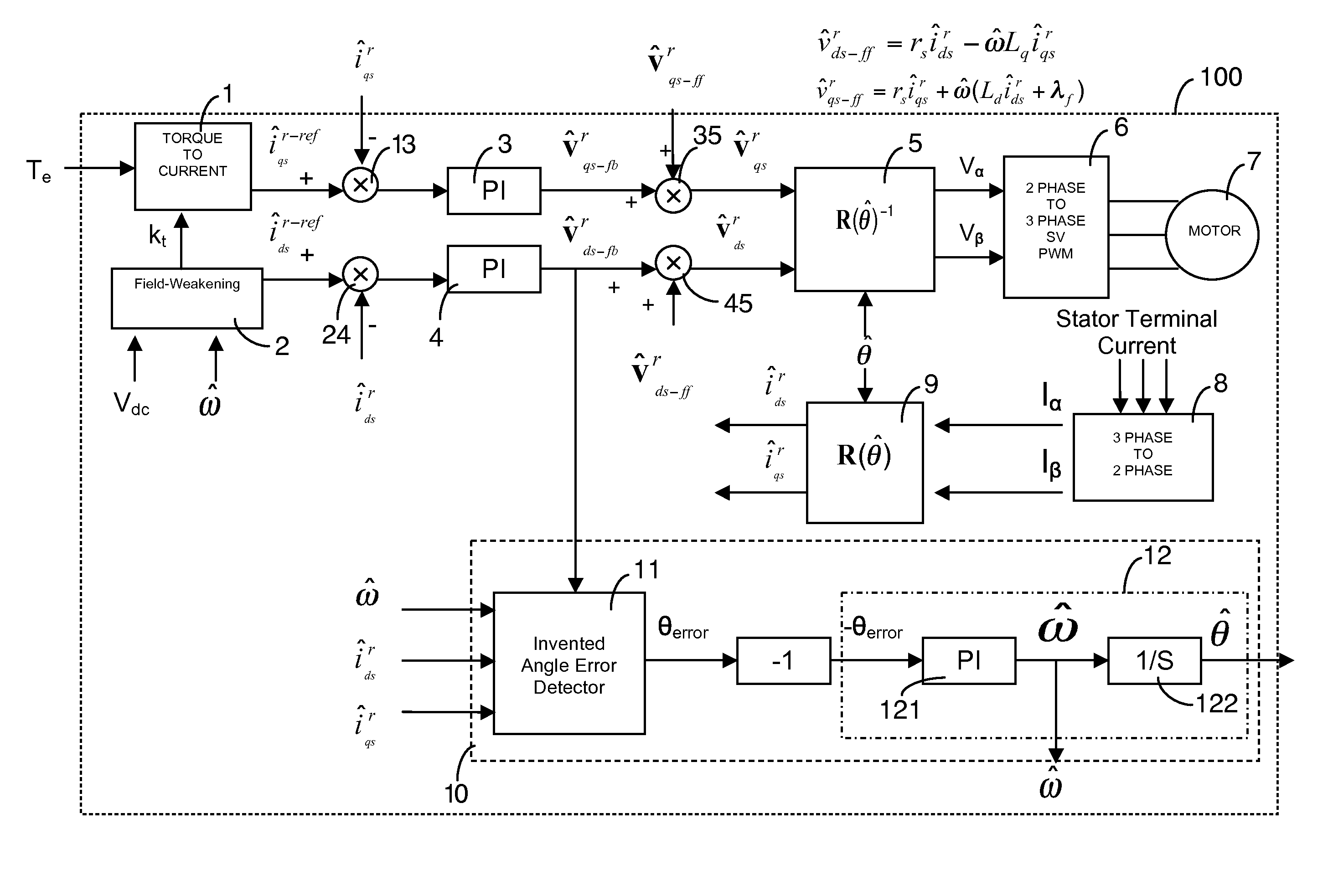
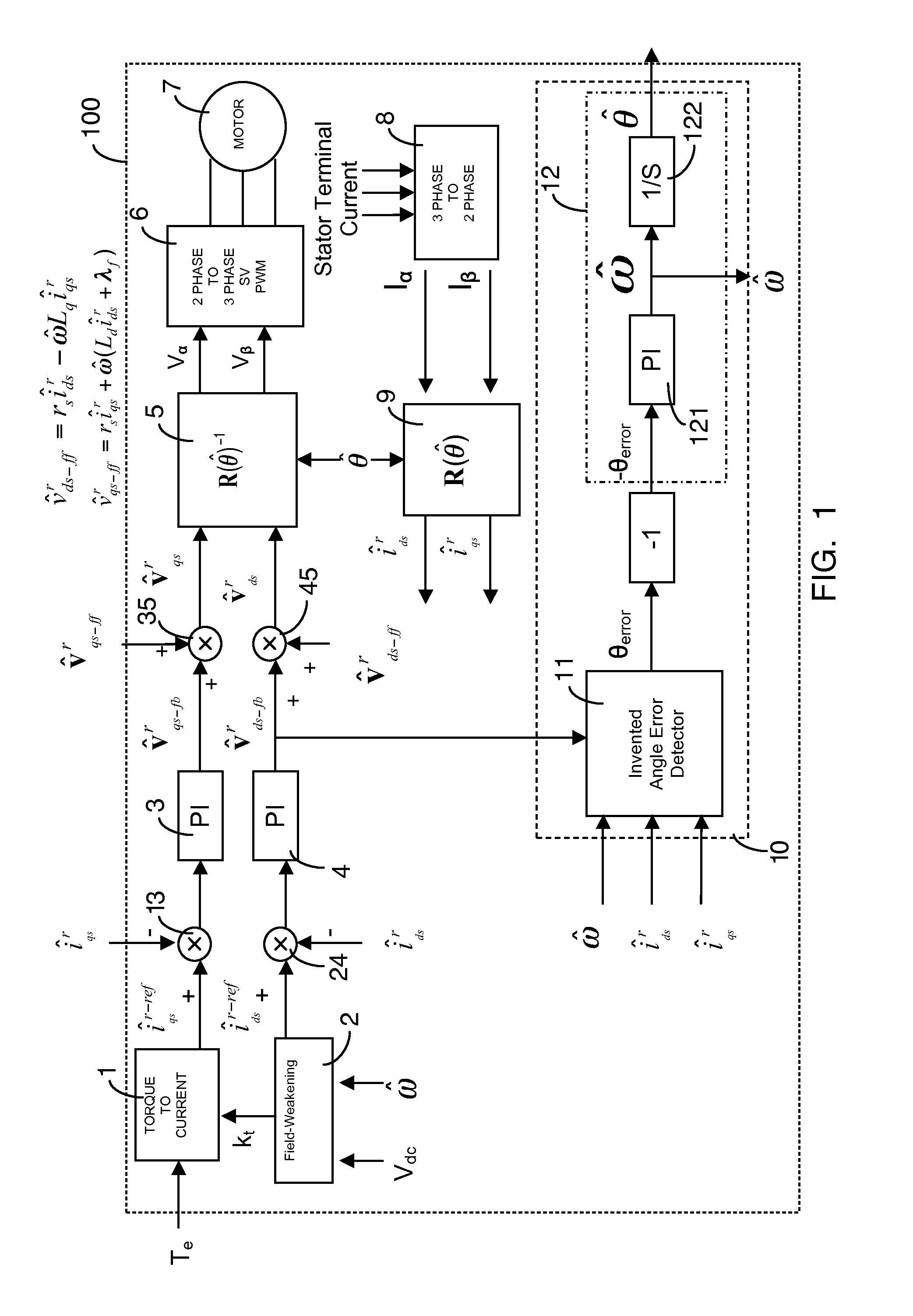
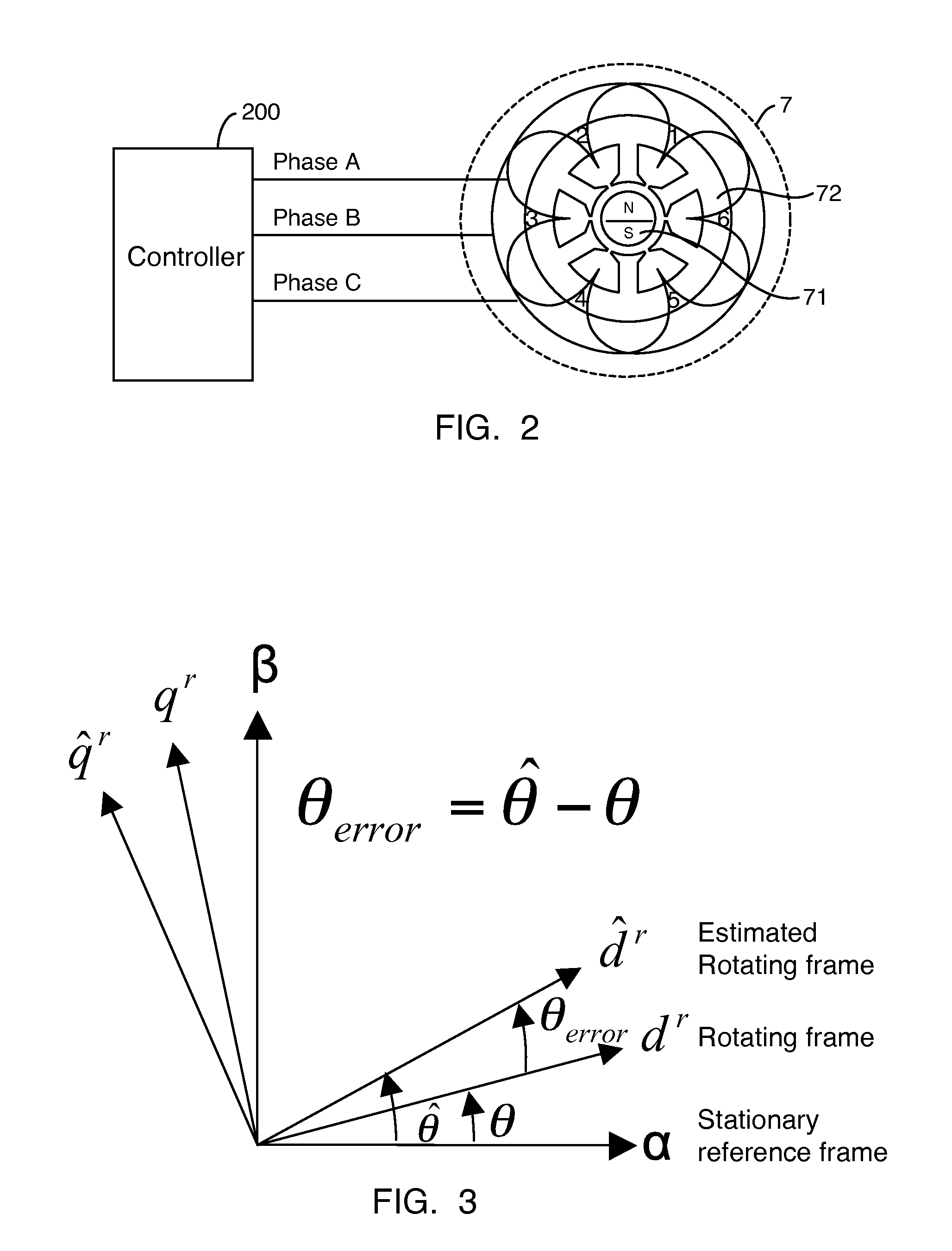
[0022]The present invention is generally directed to a control system for sensorless control of high-speed motors, including synchronous electric motors especially used in high-speed turbo machinery, such as turbo blowers and turbo compressors. Preferably, the control system is used with synchronous electric motors, such as AC synchronous motors, interior permanent magnetic motors, surface permanent magnetic motors, and the like. FIG. 2 illustrates an embodiment for position-sensorless control in accordance with the present invention, wherein a controller is connected to a motor for operation thereof. FIG. 7 illustrates an alternate embodiment for position-sensorless control in accordance with the present invention, wherein a controller is connected to a motor serving as the power train for a blower or compressor.

[0023]FIG. 1 provides a block diagram of a control system 100 configured as a preferred embodiment of the present invention. The sequence of the block diagram represents th...


PUM


Abstract

This invention provides an advanced position and velocity estimation scheme used in a position-sensorless control system for synchronous operation of an electric motor. The system includes an electric motor having a stator and a rotor; an inverter for powering the electric motor; and a controller for controlling the inverter. The controller utilizes a control system comprising a rotor angle and angular velocity estimation block; an estimated angle error detector block; a field-weakening block; and a torque-to-current converter block, all of which operate to generate control commands for operation of the motor.

Description

CROSS-REFERENCE TO RELATED APPLICATION[0001]This application claims the benefit of U.S. Provisional Application No. 61 / 110,285 filed Oct. 31, 2008, which is incorporated herein by reference.TECHNICAL FIELD OF THE INVENTION[0002]The present invention generally relates to the control of synchronous motors. More specifically, the present invention relates to a system and method for position-sensorless control of a synchronous electric motor using position and velocity estimation during motor operation.BACKGROUND OF THE INVENTION[0003]For high-speed synchronous motors, many types of motor control technologies have been adopted. Vector control is an accurate method of synchronous motor operation. Such a control system, however, is computationally intensive. A vector control method typically maps three-phase motor voltages and currents into a two-axis system. To accomplish this mapping, the vector control system requires precise rotor information, for example, rotor angular position and s...

Claims


Application Information

Patent Timeline
IPC IPC(8): H02P21/00H02P6/18
CPCH02P21/0089H02P21/18
Inventor KWON, JEONG HYECKCLARK, EDWARD A.AGRAWAL, GIRIDHARI L.
Owner R & D DYNAMICS
Why Eureka
Try Eureka