Metal wear detection apparatus and method employing microfluidic electronic device

a technology of electronic devices and metals, applied in the direction of measurement devices, resistance/reaction/impedence, instruments, etc., can solve the problems of increasing the population and size of particles, generating small wear particles with sizes in the range of 1-10 microns (m), and taking time to generate wear information. , to achieve the effect of rapid respons

Active Publication Date: 2010-05-06
THE UNIVERSITY OF AKRON
View PDF25 Cites 77 Cited by
  • Summary
  • Abstract
  • Description
  • Claims
  • Application Information

AI Technical Summary

Benefits of technology

[0006]There remains a need for a method which permits in-situ testing of lubricants that allows a rapid response when wear p

Problems solved by technology

However, over time, small wear particles with sizes in the range of 1-10 microns (μm) are generated.
The particle population and size of the particles tends to increase over time until eventually, a machine failure can result.
However, each of these methods takes time to generate wear information.
As a result, critical failures of machines may occur even when samples are sent regularly for testing.
However, the test procedure is very lengthy, and requires complicated setup and a skilled analyst (See, Roylance B. J., 2005, Tribology

Method used


Image

  • Metal wear detection apparatus and method employing microfluidic electronic device
  • Metal wear detection apparatus and method employing microfluidic electronic device
  • Metal wear detection apparatus and method employing microfluidic electronic device

Examples


example 1

Meso-Sized Capacitative Sensing Device

[0077]A meso-sized device 100 for testing the applicability of the apparatus to lubricant oils was constructed, as illustrated in FIG. 17. The device 100 consists of two parallel aluminum plates 102, 104 (cross section 2.5 cm (H)×4 cm (W)) forming a channel 106 therebetween. The plates were immersed in SAE-5W30 motor oil (with a relative permittivity ∈r ranging from about 2.1 to 2.4). Three spherical steel particles (diameters D=3.5 mm, 4.5 mm and 6.0 mm, obtained from McMaster-Carr, USA) were dropped from the top of the channel and allowed to travel to the bottom. A capacitive readout MS3110 IC chip 68 (obtained from Irvine Sensors, USA) and a NI-6220 data acquisition system (DAQ) 70 (obtained from National Instruments, USA) were used for the dynamic capacitance measurement as each particle passed through the channel 106.

[0078]The MS3110 IC chip senses the change in the differential capacitance and provides an output voltage proportional to tha...

example 2

Microscale Capacitative Sensing Device

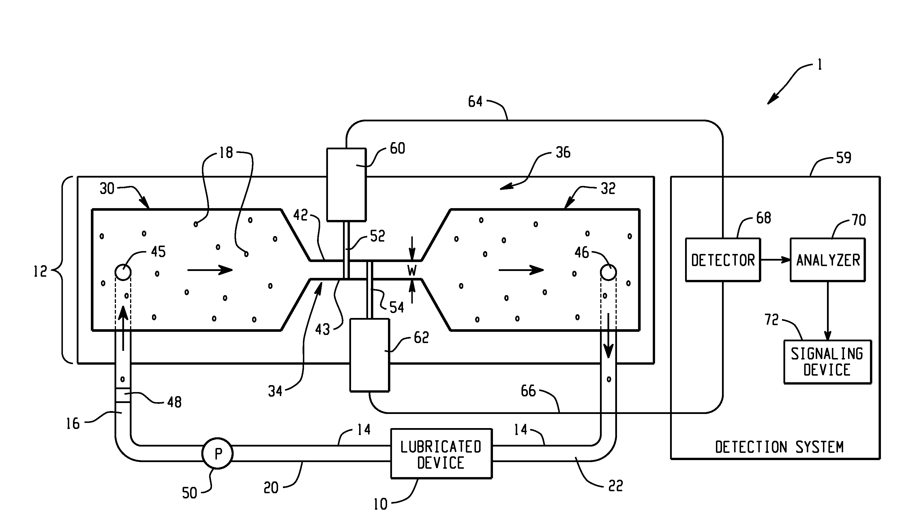
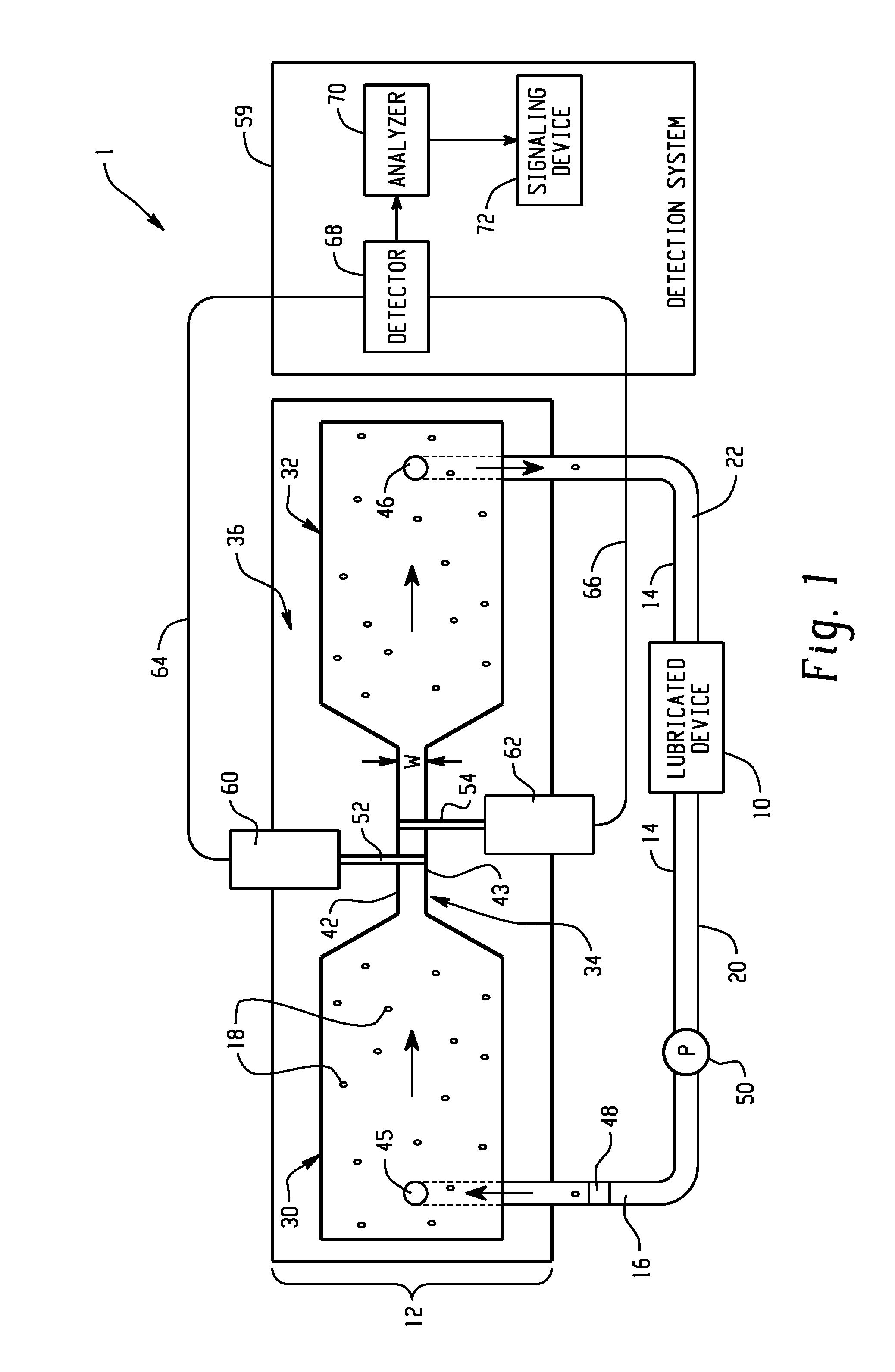
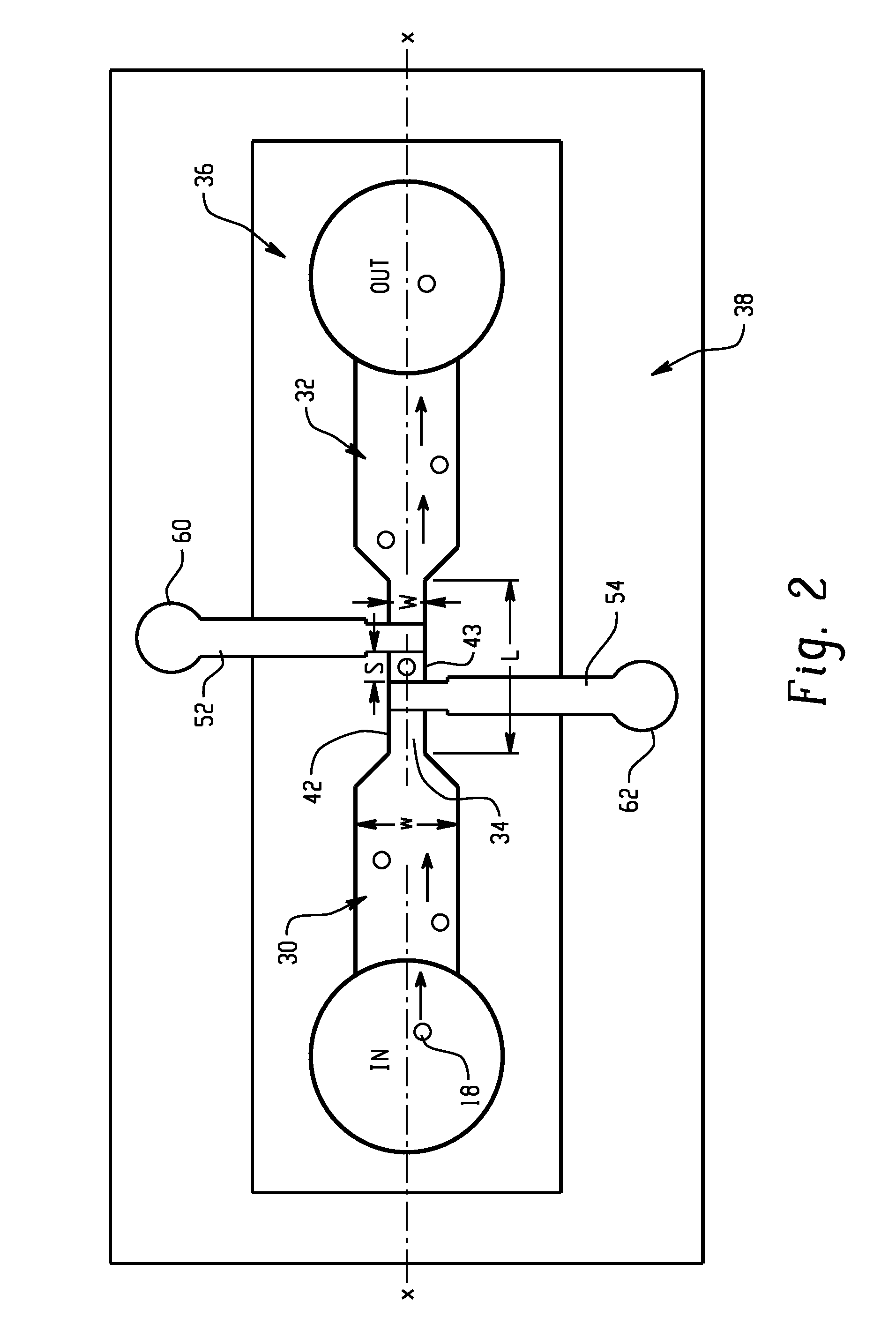
[0085]Having established the viability of the capacitative sensing technique with relatively large particles as described in Example 1, a microfluidic device 12 for detecting microscale debris particles in the lubricant oils was constructed as illustrated in FIGS. 2 and 3. The device consisted of an inlet reservoir, an outlet reservoir, a single fluidic channel 34 with dimensions of 40 μm (H)×100 μm (W)×300 μm (L), and a pair of co-planar electrodes 52, 54 for detecting microparticles 18, separated by a distance S of 20 μm. The particles were detected one at a time as they passed through the microchannel 34. The electrodes 52, 54 were connected to a MS3110 capacitance measurement chip 68, and the voltage response from the MS3110 was monitored using a NI-6220 DAQ 70.

[0086]2.1: Device Fabrication

[0087]The fabrication of the device 12 involved microchannel fabrication and electrode fabrication. The microchannels and reservoirs were fabricated on po...

example 3

Meso-Sized Inductive Sensing Device-Static Testing

[0096]To demonstrate the inductive Coulter counting principle, steel particles and aluminum particles were tested in a mesoscale device. The sensor 12 consists of a channel 6.254 mm in diameter filled with SAE 5W-30 motor oil, with a solenoid with 20 turns of 0.254 mm diameter copper wire wound around it, as illustrated in FIG. 5. The solenoid can be modeled as the equivalent circuit shown in FIG. 9, and was measured on an Agilent E4980A precision LCR meter to have Rs=0.15Ω and Ls=2.44 μH, with parasitic capacitance Cp =10.82 pF.

[0097]First, static testing was conducted. Three ferrous and conductive chromium steel N52100 particles (from McMaster-Carr, μr=50 with diameters 1 mm, 2 mm and 2.84 mm) and three nonferrous and conductive aluminum alloy 2017 particles (from McMaster-Carr, with diameters 1.98 mm, 2.34 mm, and 3.18 mm) were used. A particle was placed in the center of the channel. A sine wave generator 202 was set to produce a...


PUM


Abstract

An apparatus and a method for detection of wear particles in a lubricant are disclosed. The apparatus includes a microfluidic device including a microchannel sized for a lubricant containing wear particles to pass therethrough and first and second electrodes extending into the microchannel. A detection system is coupled with the electrodes for detection of wear particles passing through the microchannel, based on a change in capacitance of the electrodes.

Description

[0001]This application claims the benefit of U.S. Provisional Application Ser. No. 61 / 110,208, filed Oct. 31, 2008, the disclosure of which is incorporated herein in its entirety by reference.BACKGROUND[0002]The exemplary embodiment relates to the detection of wear particles in a lubrication fluid, such as oil. It finds particular application in connection with a microfluidic device for detecting or measuring an electrical property of the lubrication fluid which changes as the fluid becomes contaminated with wear particles.[0003]Machine parts, such as aircraft engines and gear boxes in which components move relative to each other, are often lubricated with a lubricant oil to reduce wear. However, over time, small wear particles with sizes in the range of 1-10 microns (μm) are generated. When abnormal wear begins, larger particles, in the range of 10 to 50 microns are generated. The particle population and size of the particles tends to increase over time until eventually, a machine ...

Claims


Application Information

Patent Timeline
IPC IPC(8): G01R27/08
CPCG01M13/02G01N33/2888G01N15/1031G01N2015/1087G01N33/2858
Inventor ZHE, JIANGDU, LICARLETTA, JOAN E.VEILLETTE, ROBERT J.
Owner THE UNIVERSITY OF AKRON
Why Eureka
Try Eureka