Fast response failure mode control methodology for a hybrid vehicle having an electric machine

a hybrid vehicle and failure mode technology, applied in the direction of electric devices, emergency power supply arrangements, constant-current supply dc circuits, etc., can solve the problem that the disconnection of the battery pack significantly limits the post-failure range of the vehicle, and achieve the effect of improving the response tim

Active Publication Date: 2010-05-06
DELPHI TECH IP LTD
View PDF10 Cites 16 Cited by
  • Summary
  • Abstract
  • Description
  • Claims
  • Application Information

AI Technical Summary

Benefits of technology

[0006]The present invention is directed to an improved control methodology for an engine-driven electric machine of a hybrid vehicle electrical system for enabling continued operation of the vehicle electrical system under failure mode conditions that require or result in disconnection of the battery pack from the electrical system. At the onset of a failure mode condition requiring disconnection of the battery pack in systems including a controlled power coupler such as a relay, the electric machine is operated as a generator and is controlled in accordance with a first mode of operation that drives the battery pack current toward zero. When the battery pack current falls below a near-zero threshold, the power coupler is activated to disconnect the battery pack from the electrical system. Once the battery pack is disconnected from the electrical system, whether by relay or fuse, the electric machine is controlled according to a second mode of operation that maintains the bus voltage of the electrical system at a specified value. In both operating modes, the electric machine is controlled based on a synchronous vector current command that is determined directly as a function of the control objective (zero battery pack current or maintaining bus voltage) for improved response time compared to a traditional torque-based control.

Problems solved by technology

In either case, the battery pack disconnection significantly limits the post-failure range of the vehicle because certain electrical loads such as the engine ignition system are required for continued operation of engine 10, and the auxiliary battery 40 can only power such loads for a limited period of time.

Method used


Image

  • Fast response failure mode control methodology for a hybrid vehicle having an electric machine
  • Fast response failure mode control methodology for a hybrid vehicle having an electric machine
  • Fast response failure mode control methodology for a hybrid vehicle having an electric machine

Examples


Embodiment Construction

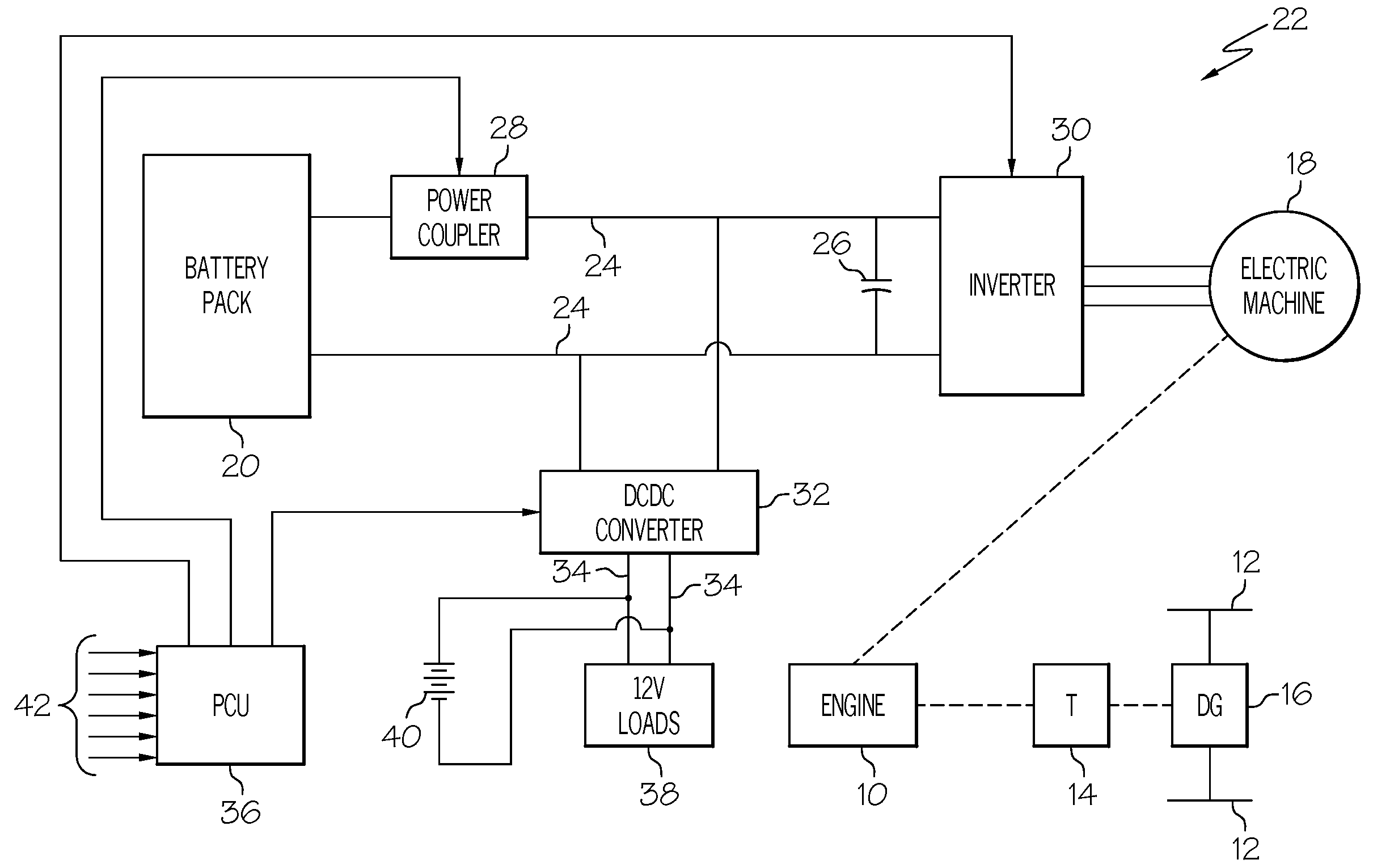
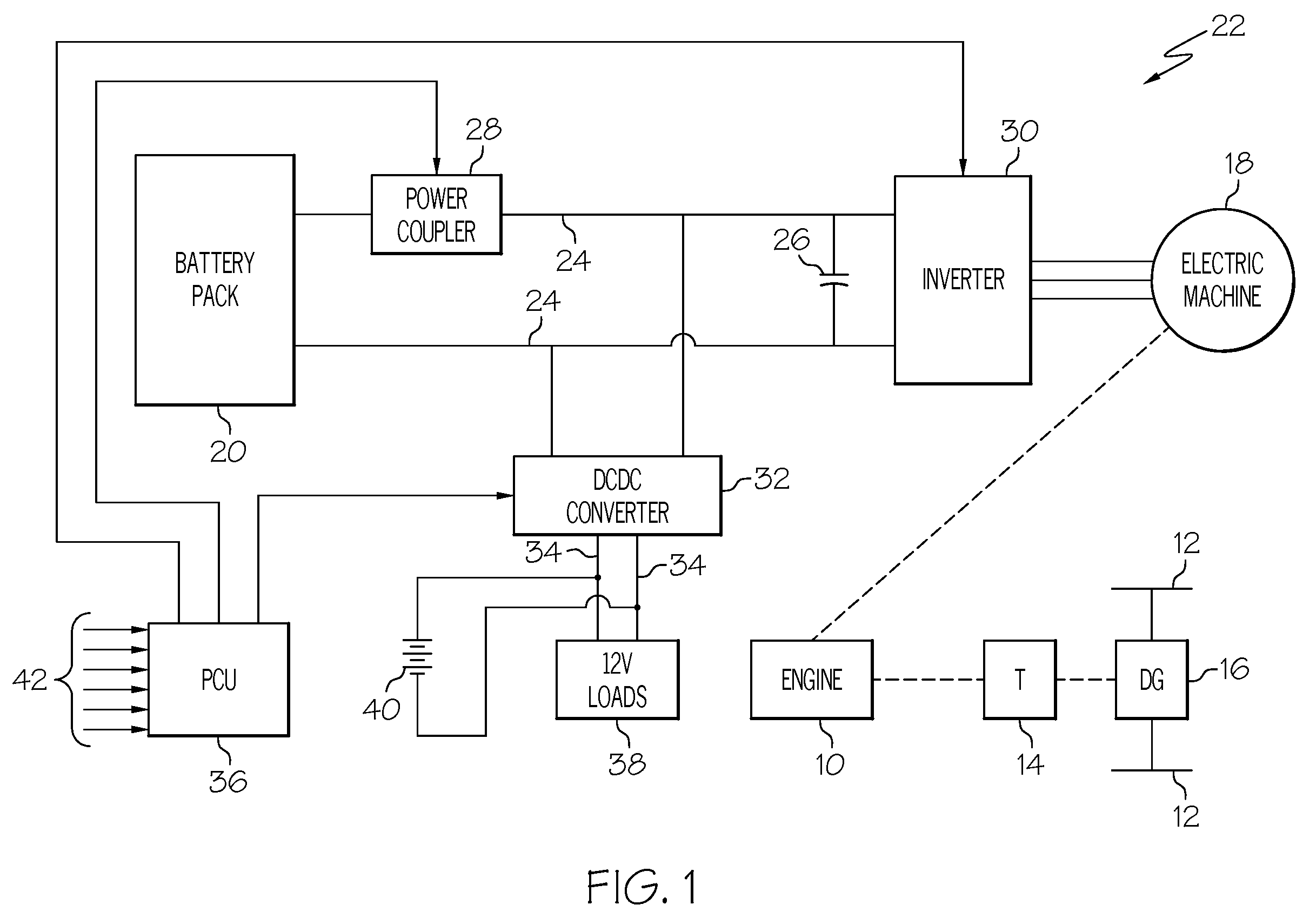
[0011]While the method of the present invention is disclosed herein in the context of the exemplary hybrid vehicle electrical system and powertrain of FIG. 1, it should be understood that the described method is applicable to any hybrid vehicle electrical system including a battery pack and an engine-driven electric machine. Virtually all hybrid vehicle electrical systems include a battery pack for storing electrical energy and an engine-driven electric machine selectively operable in a generating mode to charge the battery pack and supply power to various electrical loads, and in a motoring mode to crank the engine and to augment the engine power output. And in all such configurations, there is the possibility of a failure mode condition that requires or will result in disconnection of the battery pack from the vehicle electrical system. If a contactor device such as a relay is used to disconnect the battery pack, the battery pack current is first reduced to ensure safe and reliabl...


PUM


Abstract

A control methodology for an engine-driven electric machine of a hybrid vehicle electrical system for enabling continued operation of the vehicle electrical system under failure mode conditions that require or result in disconnection of the battery pack from the electrical system. At the onset of a fault condition requiring battery disconnection, the electric machine is controlled to drive the battery pack current toward zero before disconnecting the battery pack. Once the battery pack is disconnected, whether by relay or fuse, the electric machine is controlled to maintain the bus voltage of the electrical system at a specified value. In both operating modes, the electric machine is controlled based on a synchronous vector current command that is determined directly as a function of the control objective (zero battery pack current or maintaining bus voltage) for improved response time compared to a traditional torque-based control.

Description

RELATED APPLICATIONS[0001]The present invention is a continuation-in-part of co-pending U.S. patent application Ser. No. 12 / 290,974, filed Nov. 5, 2008, and assigned to the assignee of the present patent application.FIELD OF THE INVENTION[0002]The present invention is directed to a failure-mode battery disconnect method for a hybrid vehicle electrical system including a high voltage battery pack and an engine-driven electric machine operable in generating and motoring modes, and more particularly to a control method for the electric machine that permits continued operation of the engine and electric machine after the battery pack is disconnected from the electrical system.BACKGROUND OF THE INVENTION[0003]The fuel efficiency of a motor vehicle can be considerably enhanced with a hybrid system including an electric machine coupled to the engine, a high voltage battery pack, and a power electronics system for interconnecting the electric machine, the battery pack and the electrical loa...

Claims


Application Information

Patent Timeline
Patent Type & Authority Applications(United States)
IPC IPC(8): H02H7/08
CPCB60K6/46Y10T307/631B60L3/0046B60L3/0069B60L3/0092B60L3/04B60L3/12B60L15/025B60L2220/14B60L2220/18B60W10/26B60W20/00Y02T10/6217Y02T10/6226Y02T10/643Y02T10/7077Y10T307/593Y10T307/549Y10T307/696Y10T307/615Y10T307/50B60W10/08Y02T10/70B60L3/00B60W10/28B60W20/50B60L50/16B60K6/485B60K6/48B60K2006/4833Y02T10/62Y02T10/64Y02T10/7072
Inventor WALTERS, JAMES E.FATTIC, GERALD T.
Owner DELPHI TECH IP LTD
Why Eureka
Try Eureka