Tool and tool correction method

Inactive Publication Date: 2010-05-06
YAMAGISHI KOU
View PDF7 Cites 18 Cited by
  • Summary
  • Abstract
  • Description
  • Claims
  • Application Information

AI Technical Summary

Benefits of technology

[0020]With the above-explained structure, the present invention can provide a tool and a tool correction method which are capable of precisely measuring a distance from a reference point such as a mechanical origin to a cutting edge, even if the cutting edge is small in diameter, thereby allowing the cutting edge to be precisely moved to a mac

Problems solved by technology

Therefore, there is a high possibility that a target to be measured is broken due to a contact pressure of the gauge head 101 in the contact system employing the gauge head 101 such as a probe for the measuring medium Z, and there is a problem that, if the gauge head 101 is an electrode or the like, there occurs electric discharge due to insulation destruction exerted by a slight air gap, and precise measurement becomes difficult.
In addition, the optical system employing the light 102 as the measuring medium Z entails a problem that there occurs aberration due to boundary refraction of a target to be measured, and an error is prone to occur in measurement result, and further, the reflection system employing the undulation 103 such as a sonic wave or an electromagnetic wave as the measuring medium Z does not function if a target to be measured fails to meet a predetermined mass, and thus, measurement per se becomes difficult relative to a tool of a very small diameter.
Measurement by optical magnification-type stereoscopic vision or measurement by optical imaging also entails a similar problem in that measurement becomes difficult due to a reason that resolution does not increase.
This is a common problem concerning a variety of tools such as rotary blades or non-rotary blades, including an end mill, a drill, and a spring-necked turning tool, and further, is similar to an electrode, etc., for electric discharge machining other than these blades as well.

Method used


Image

  • Tool and tool correction method
  • Tool and tool correction method
  • Tool and tool correction method

Examples


Embodiment Construction

[0032]Hereinafter, one embodiment of the present invention will be described referring to the drawings.

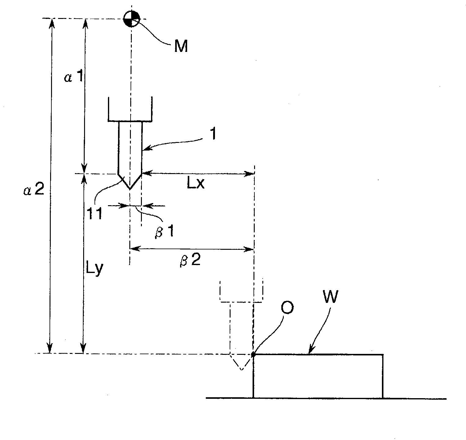
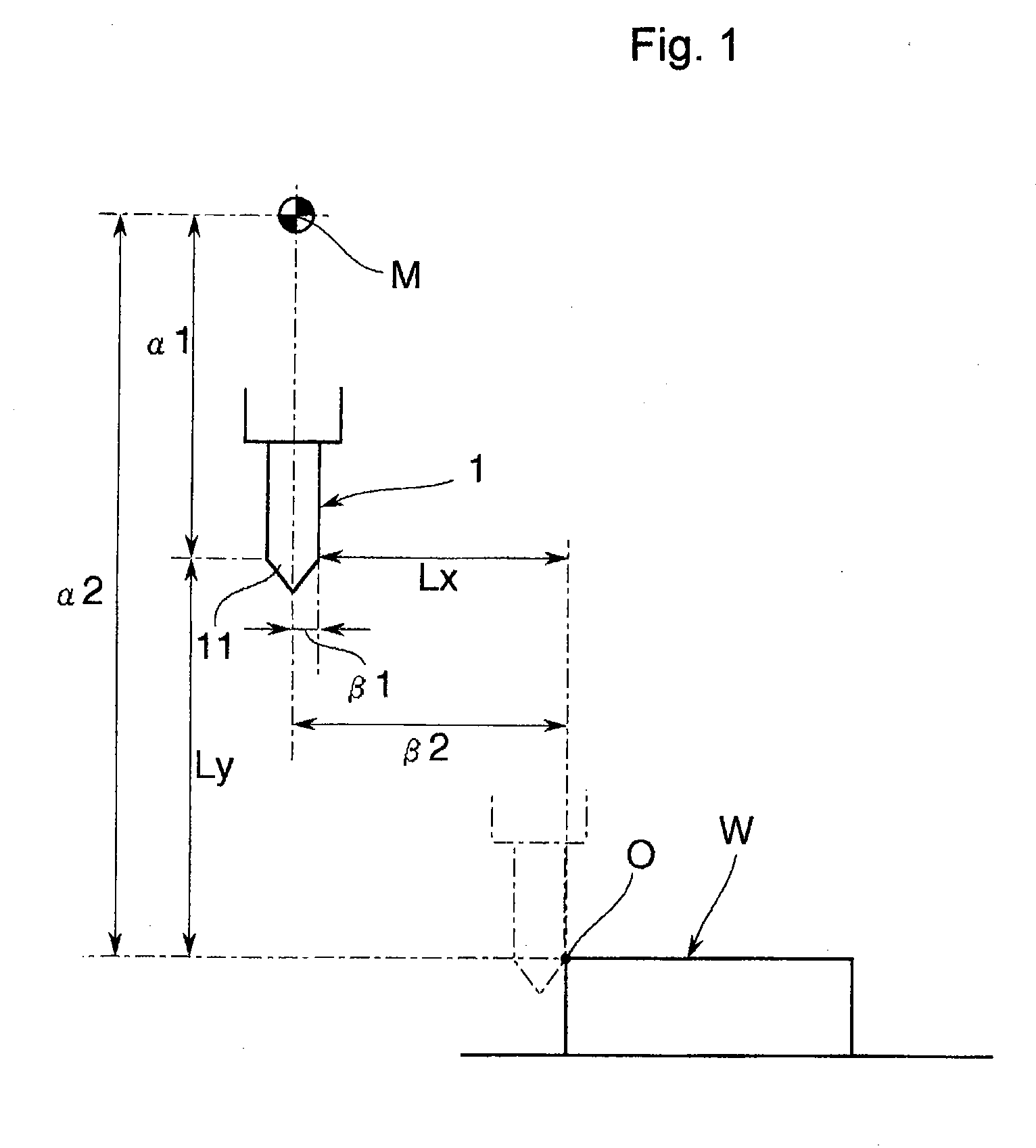
[0033]A tool of the embodiment is used by mounting it on an NC machine tool such as a machining center. As already exemplarily described with respect to a longitudinal direction, in machines of this type, as shown in FIG. 1, a machining origin O on a work piece W is recognized based upon an offset quantity α2 in a longitudinal direction and an offset quantity β2 from a mechanical origin M in a mechanical coordinate system; a movement route of a tool 1, instructed in a machining program created with reference to the machining origin O, is converted into a mechanical coordinate system by employing the offset quantities α2, β2; and movement of the tool 1 is numerically controlled under this mechanical coordinate system.

[0034]At this time, by employing offset quantities α2, β2 from the mechanical origin M to the machining origin O and relative distances α1, β1 from the mechanical origi...


PUM

PropertyMeasurementUnit
Diameteraaaaaaaaaa

Abstract

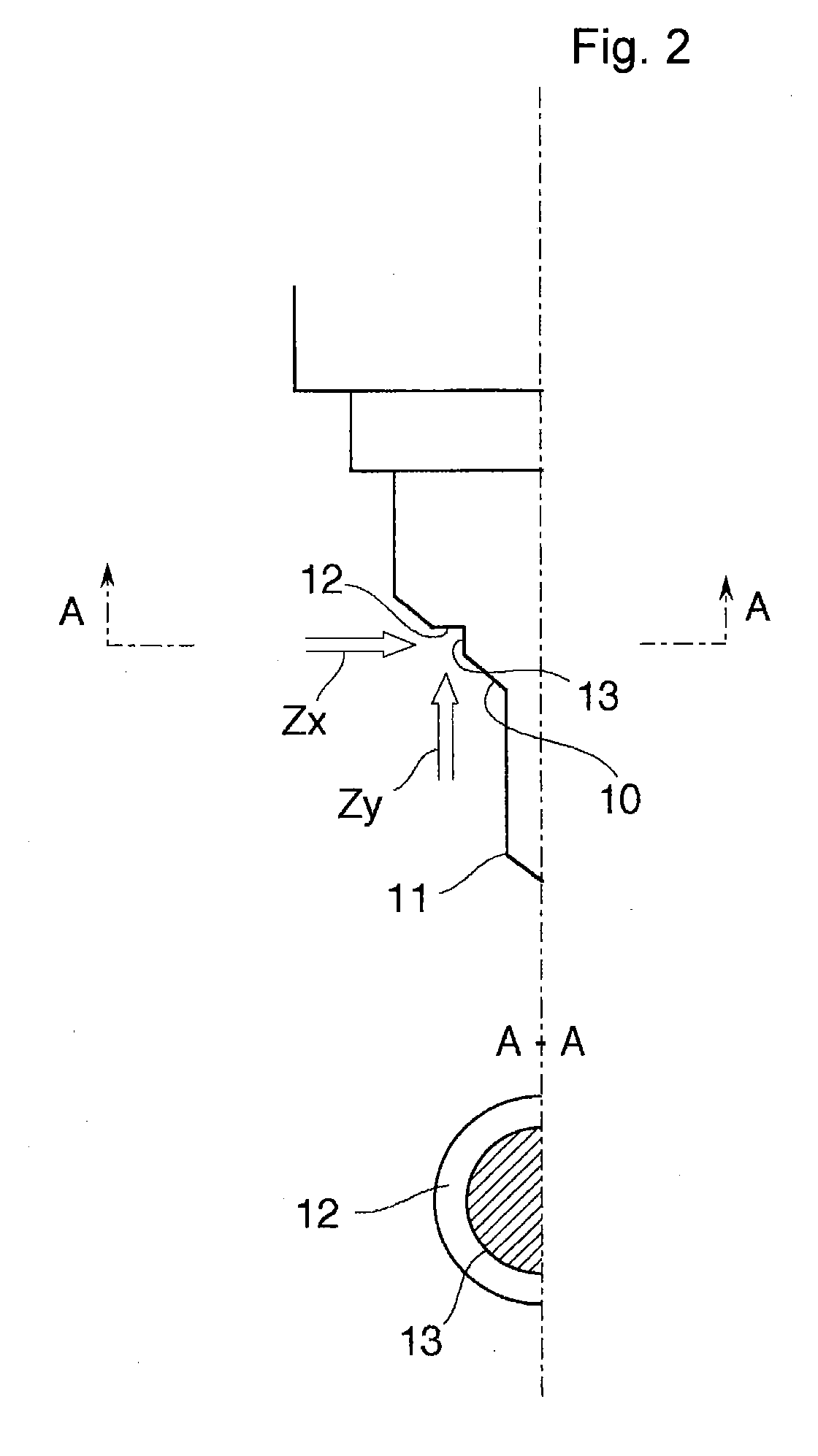
Provided is a tool which is capable of precisely measuring a distance from a reference point such as a mechanical origin to a cutting edge, even where the cutting edge is small in diameter, thereby allowing the cutting edge to be precisely moved to a machining origin which is a machining start position. Targets (12), (13) are provided at a site displaced from a cutting edge (11) which is a machining site to a thicker base side, on the tool designated by numeral (1), for applying machining to a work piece (W). These targets are formed in an irregular shape for acting measuring mediums (Zy), (Zx) such as a probe or an electrode for contact-type measurement, light for optical measurement, or a sonic wave for displacement-type measurement, and further, light required for optical magnification-type stereoscopic vision or optical imaging.

Description

TECHNICAL FIELD[0001]The present invention relates to a tool and a tool correction method which are capable of appropriately detecting a position of a cutting edge or the like when a tool of a minute diameter is mounted on a spindle of a machine tool such as a machining center or an NC (Numerically Controlled) milling machine.BACKGROUND ART[0002]Machining such as drilling or cutting, as shown in FIG. 7, is performed by mounting a tool 1 such as an end mill on a tooling 2, and further, mounting this tooling 2 on a spindle 3 of a processing machinery such as a machining center or a lathe. As the processing machinery also, an NC (Numerically Controlled) machine tool has become prevalent.[0003]In machine tools of this type, in general, a machining origin O is recognized based upon an offset quantity α2 from a mechanical origin M in a mechanical coordinate system; a movement route of a tool, instructed in a machining program created with reference to the machining origin O, is converted ...

Claims


Application Information

Patent Timeline
IPC IPC(8): B23Q17/22B23Q17/24
CPCB23Q17/2233B23Q17/24Y10T409/303752Y10T409/3084
Inventor YAMAGISHI, KOU
Owner YAMAGISHI KOU
Why Eureka
Try Eureka