Distance measurement apparatus and windshield

Pending Publication Date: 2021-07-15
SONY CORP
View PDF43 Cites 0 Cited by
  • Summary
  • Abstract
  • Description
  • Claims
  • Application Information

AI Technical Summary

Benefits of technology

The patent text explains a problem with current technology that tries to prevent loss during the passage through laminated glass. This technology requires complicated adjustments and the use of a reflection suppression structure, making the distance measurement apparatus more complicated. The technical effect of this patent is to provide a simpler solution for preventing loss during passage through laminated glass.

Problems solved by technology

Meanwhile, in the case where a passenger compartment is equipped with a radar to detect a target outside a vehicle, the radar suffers a loss due to passage through a glass surface included in the windshield.

Method used


Image

  • Distance measurement apparatus and windshield
  • Distance measurement apparatus and windshield
  • Distance measurement apparatus and windshield

Examples


first embodiment

1. First Embodiment

[Windshield]

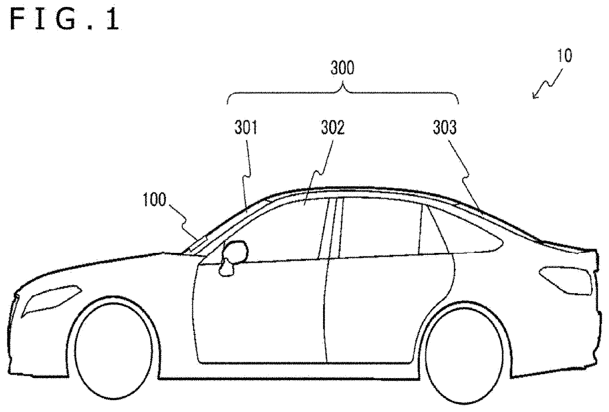
[0032]FIG. 1 is a diagram illustrating an example of an external side view of an automotive vehicle 10 in an embodiment of the present technology.

[0033]The vehicle 10 includes a transparent or translucent windshield 300 to allow visibility into the vehicle from outside. The windshield 300 on the front side in a direction of travel is referred to as a front windshield 301. The windshield 300 on a lateral side is referred to as a side windshield 302. The windshield 300 on the rear side is referred to as a rear windshield 303.

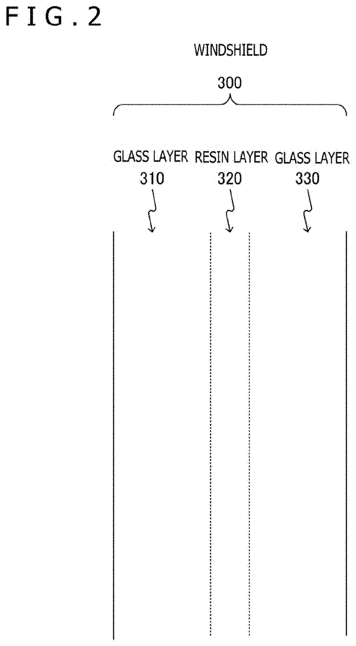
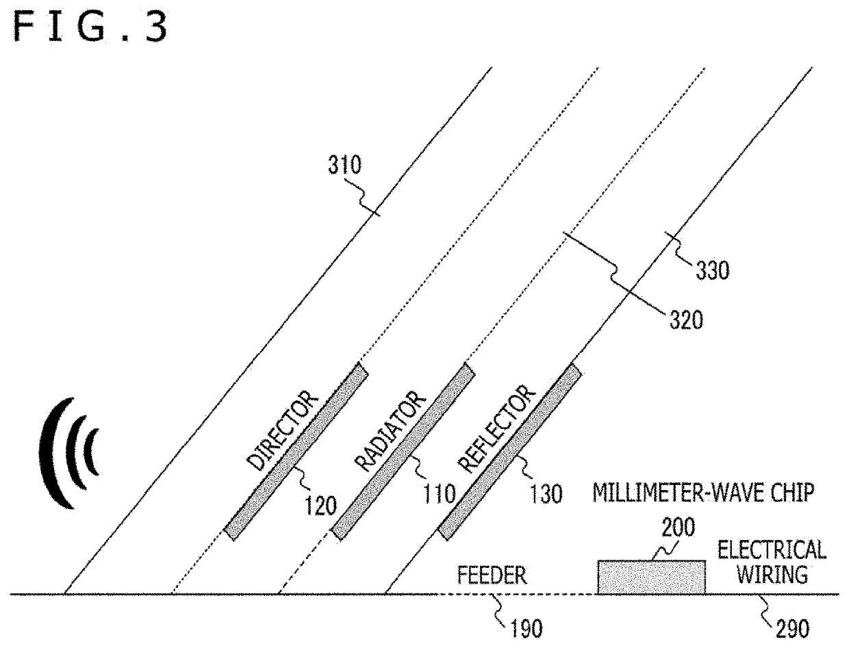
[0034]The windshield 300 often includes laminated glass. In the present embodiment, we assume that part of an antenna 100 is embedded in the front windshield 301 by taking advantage of this laminated glass structure.

[0035]The antenna 100 is designed to achieve transmission and reception of radio waves by a millimeter-wave radar. The millimeter-wave radar (Radio Detection And Ranging) detects an object by radiating radio waves ranging...

first modification example

[0064]FIG. 6 is a diagram illustrating an example of installation of the antenna 100 to the windshield 300 in a first modification example of the first embodiment of the present technology.

[0065]Although it has been assumed, in the above first embodiment, that the radiator 110, the director 120, and the reflector 130 are used as the antenna 100, the reflector 130 is omitted in this first modification example. This provides a simpler structure of the antenna 100 albeit with lower radiation efficiency of radio waves.

second modification example

[0066]FIG. 7 is a diagram illustrating an example of installation of the antenna 100 to the windshield 300 in a second modification example of the first embodiment of the present technology.

[0067]Although it has been assumed, in the above first embodiment, that the radiator 110, the director 120, and the reflector 130 are used as the antenna 100, the director 120 and the reflector 130 are omitted in this second modification example. This provides a simpler structure of the antenna 100 although the antenna 100 is no longer able to control radio wave directivity.

[0068]As described above, according to the first embodiment of the present technology, it is possible to reduce a passage distance in the windshield 300 by embedding at least part of the antenna 100 in the windshield 300, thus suppressing loss of radio waves. Further, the millimeter-wave chip 200 can be installed externally to the windshield 300, thus permitting maintenance on the millimeter-wave chip 200 in the event of a def...


PUM


Abstract

Radar loss caused by a windshield having laminated glass in a vehicle is suppressed with a simple configuration.An antenna's radiation section is disposed inside the windshield of a vehicle having a plurality of layers. The radiation section not only radiates radio waves but also receives reflected waves of the radio waves from a target. A distance measurement information generation section is connected to the radiation section. The distance measurement information generation section measures a distance to the target on the basis of the radiated radio waves and the reflected waves from the target and generates distance measurement information.

Description

TECHNICAL FIELD[0001]The present technology relates to a distance measurement apparatus and more particularly to a distance measurement apparatus for measuring a distance between a vehicle and a target by using radio waves having a given wavelength and to a windshield.BACKGROUND ART[0002]Three-layer laminated glass having glass stacked on a resin film layer is often chosen as a windshield of an automotive vehicle for passenger safety. Meanwhile, in the case where a passenger compartment is equipped with a radar to detect a target outside a vehicle, the radar suffers a loss due to passage through a glass surface included in the windshield. In order to suppress this loss, for example, a system for adjusting a radar incident angle has been proposed (refer, for example, to PTL 1).CITATION LISTPatent Literature[PTL 1][0003]Japanese Patent Laid-open No. 2016-070916SUMMARYTechnical Problem[0004]In order to suppress a loss due to passage through laminated glass, the above conventional techn...

Claims


Application Information

Patent Timeline
IPC IPC(8): G01S13/931B60J1/00
CPCG01S13/931G01S2013/93276B60J1/001G01S7/03H01Q1/325H01Q1/1271H01Q19/28
Inventor UCHIDA, SHIGENORITAKEDA, TAKAHIRO
Owner SONY CORP
Why Eureka
Try Eureka