Unlock instant, AI-driven research and patent intelligence for your innovation.

Crenelated turbine nozzle

Active Publication Date: 2010-05-06
GENERAL ELECTRIC CO
View PDF15 Cites 22 Cited by
  • Summary
  • Abstract
  • Description
  • Claims
  • Application Information

AI Technical Summary

Benefits of technology

[0023]A turbine nozzle includes a row of vanes extending radially between annular outer and inner bands. The outer band includes a pair of radial flanges defining an annular seal groove therebetween. One of the flanges is crenelated to improve nozzle life.

Problems solved by technology

Since the first stage turbine nozzle first receives the high temperature combustion gases from the combustor it is subject to an extremely hostile operating environment that affects the useful life thereof.
Thermal restraint as well as structural rigidity are correspondingly reduced by circumferentially segmenting the nozzle bands, which correspondingly increases the complexity of the design by requiring suitable spline seals between the segmented bands.
However, as the number of vanes in each band segment increases, the significant problem of thermal restraint of the individual vanes also increases, with an associated increase in thermal stress where the vanes meet the integral bands.
Adding to the complexity of the design of modern turbine nozzles, is their mounting configuration in the engine itself.
In one conventional design of a small aircraft engine, a fully annular or unitary turbine nozzle is used without any circumferential segmentation of its outer and inner bands for reducing the structural complexity thereof, but at the expense of nozzle life.
However, operating experience has shown that this type of turbine nozzle has a finite useful life substantially less than that typically found for segmented turbine nozzles.

Method used


Image

  • Crenelated turbine nozzle
  • Crenelated turbine nozzle
  • Crenelated turbine nozzle

Examples


Embodiment Construction

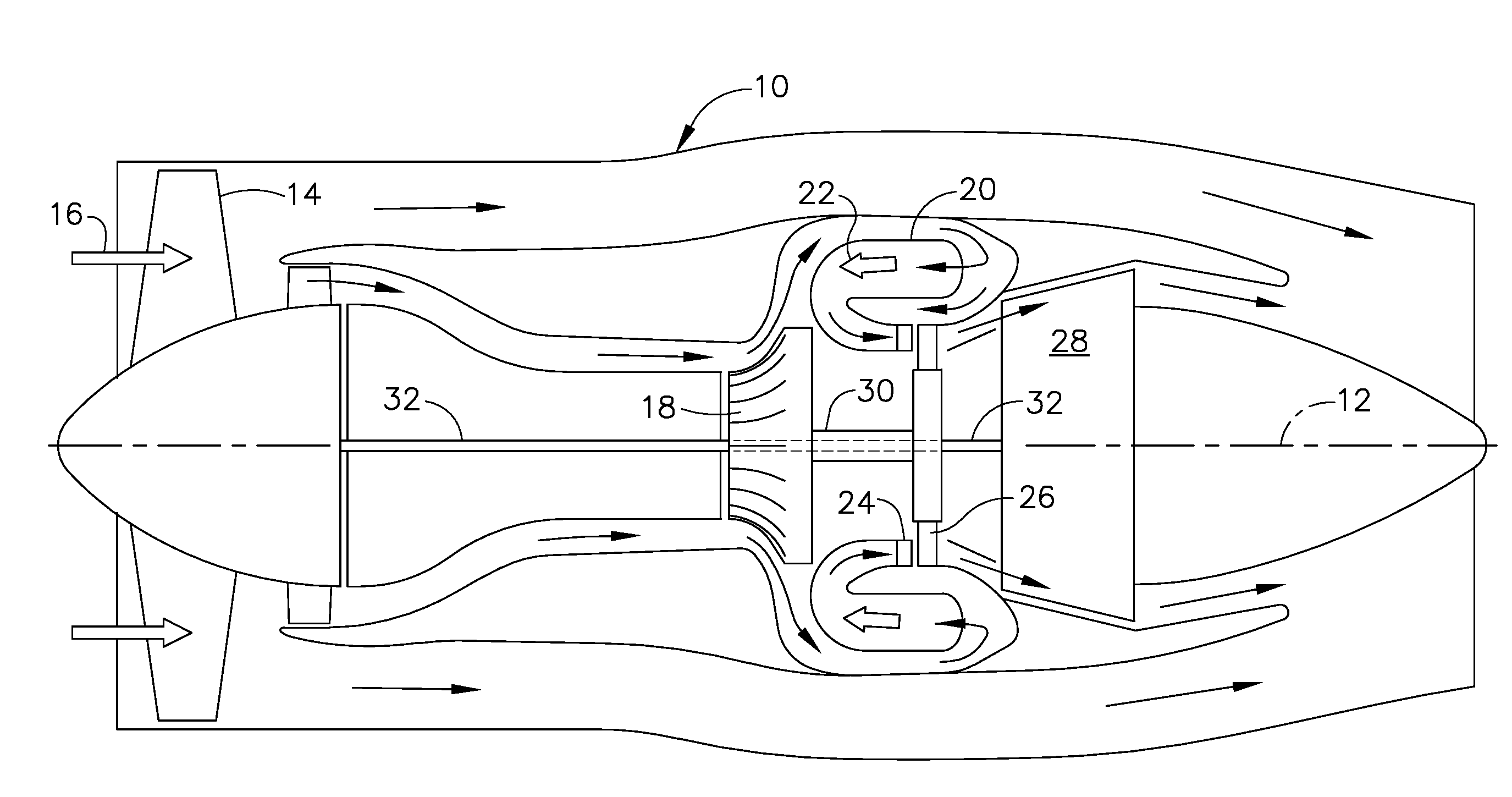
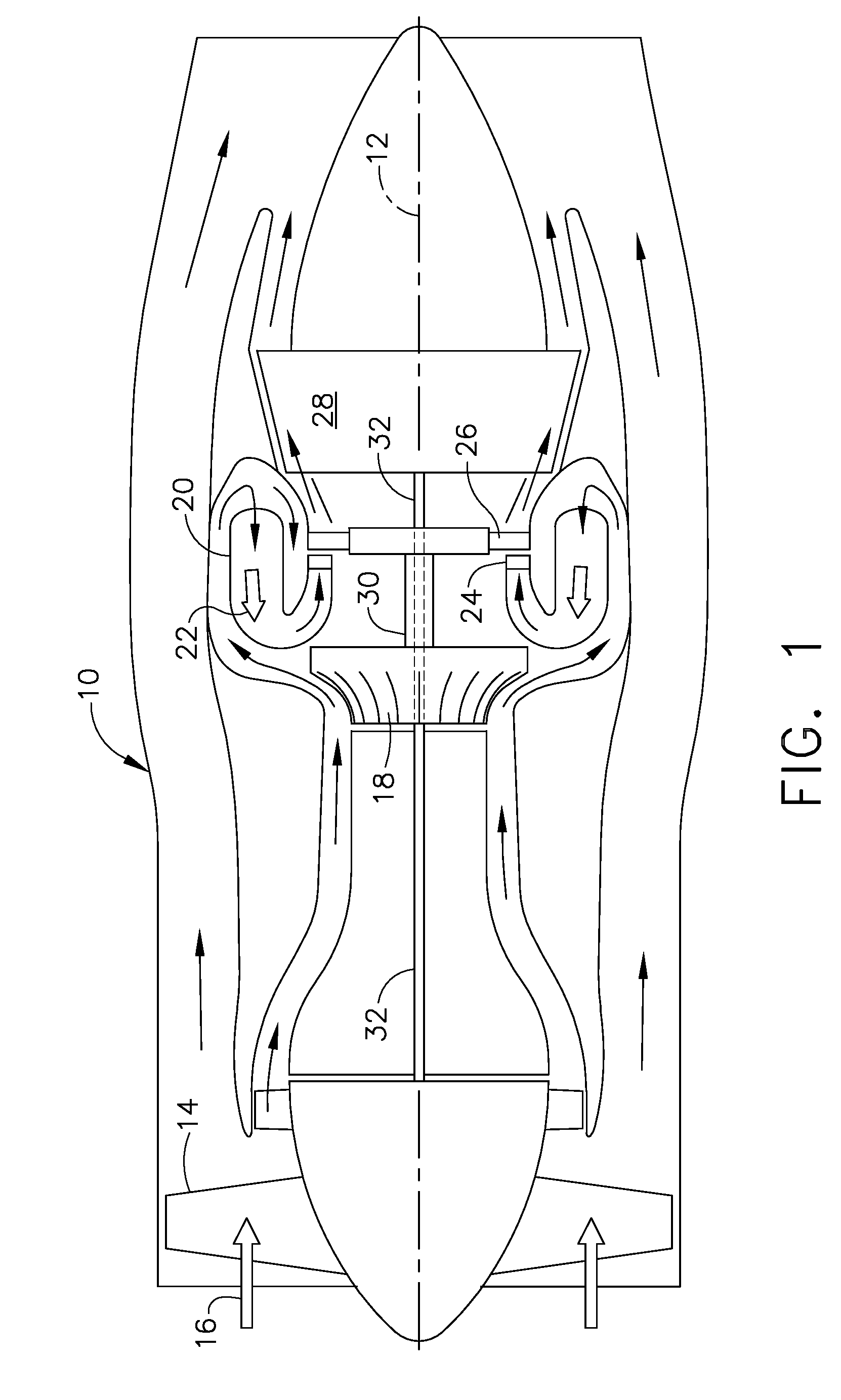
[0036]Illustrated schematically in FIG. 1 is a turbofan aircraft gas turbine engine 10 which is axisymmetrical about a longitudinal or axial centerline axis 12. The engine includes a fan 14 at its forward end which receives ambient air 16.

[0037]The air 16 is initially pressurized by the rotor blades of the fan 14 and channeled downstream to a centrifugal compressor 18 that further pressurizes the air.

[0038]The pressurized compressor air is then channeled axially downstream into an annular combustor 20 wherein the air is mixed with fuel and ignited for generating hot combustion gases 22. The exemplary combustor 20 illustrated in FIG. 1 is a reverse flow combustor in which the pressurized compressor air is initially channeled to the aft end of the combustor wherein it reverses direction upstream for generating the combustion gases therein, with the combustor being configured to again reverse direction of the combustion gases into the axially downstream direction in a conventional conf...


PUM


Abstract

A turbine nozzle includes a row of vanes extending radially between annular outer and inner bands. The outer band includes a pair of radial flanges defining an annular seal groove therebetween. One of the flanges is crenelated to improve nozzle life.

Description

BACKGROUND OF THE INVENTION[0001]The present invention relates generally to gas turbine engines, and, more specifically, to turbine nozzles therein.[0002]In a gas turbine engine, air is pressurized in a compressor and mixed with fuel in a combustor for generating hot combustion gases. The combustion gases are discharged from the combustor through a first stage turbine nozzle that channels the combustion gases into a row of turbine rotor blades which extract energy therefrom for powering the compressor.[0003]The high pressure turbine (HPT) may have one or more turbine stages and is typically followed by a multistage low pressure turbine (LPT) that extracts additional energy from the combustion gases for powering an upstream fan in the typical turbofan aircraft engine configuration.[0004]Since the first stage turbine nozzle first receives the high temperature combustion gases from the combustor it is subject to an extremely hostile operating environment that affects the useful life th...

Claims


Application Information

Patent Timeline
IPC IPC(8): F01D9/02F04D29/54
CPCF01D9/041F01D25/246F05D2240/55F05D2220/3212F05D2250/182Y02T50/671Y02T50/60F01D25/243
Inventor SCOGGINS, PATRICK JARVISLAFLEN, JAMES HARVEYLEE, CHING-PANGFROST, WILSON
Owner GENERAL ELECTRIC CO
Features
  • R&D
  • Intellectual Property
  • Life Sciences
  • Materials
  • Tech Scout
  • Unparalleled Data Quality
  • Higher Quality Content
  • 60% Fewer Hallucinations
Learn More