Centrifugal Pump Comprising a Spiral Housing

a centrifugal pump and spiral housing technology, which is applied in the direction of machines/engines, stators, liquid fuel engines, etc., can solve the problems of damage to electronic components, inability to avoid liquid or vapor passing, etc., and achieve the effect of reducing the overall space required for centrifugal pumps

Inactive Publication Date: 2010-05-06
CONTINENTAL AUTOMOTIVE GMBH
View PDF8 Cites 7 Cited by
  • Summary
  • Abstract
  • Description
  • Claims
  • Application Information

AI Technical Summary

Benefits of technology

[0006]An object of the invention, is to create a centrifugal pump having a spiral housing, in which liquid or vapor from the wet chamber enclosing the rotor is prevented from entering the dry chamber.
[0008]Due to the continuous cup-shaped configuration of the second housing part, it is possible to completely prevent liquid from the wet chamber N getting into the dry chamber T. There is advantageously no need to divide the wet chamber N from the dry chamber T through sealing elements by way of a separate can. A continuous separation of the dry chamber T from the wet chamber N is ensured even over prolonged operating times. The arrangement of a separate can is advantageously dispensed with altogether.
[0009]In a preferred embodiment of the invention the outer area of the second housing part has an outline of curved longitudinal section perpendicular to the direction of flow of the medium flowing in from the inlet E. The precise curved profile is engineered to optimize the fluid mechanics of the spiral housing. This is an advantageous way of adjusting the flow conditions in the spiral housing to an optimum setting, so that the overall space required for the centrifugal pump is reduced. The invention further relates to the use of the centrifugal pump as a coolant centrifugal pump in a motor vehicle. Coolant centrifugal pumps in motor vehicles have to function over a prolonged time, there being a need to avoid damaging the electronic components in the dry chamber T. The use of the centrifugal pump as a coolant centrifugal pump in a motor vehicle is therefore particularly advantageous.

Problems solved by technology

A disadvantage being that it is necessary to arrange sealing elements between the one part of the spiral housing and the can avoid liquid or vapor from the wet chamber getting into the dry chamber.
Over prolonged operating times, as the seal gradually becomes porous, or when subjected to vibrations acting on the centrifugal pump, it is often not possible to avoid liquid or vapor passing from the wet chamber into the dry chamber.
This results, in damage to electronic components, which in addition to the stator are also arranged in the dry chamber.

Method used


Image

  • Centrifugal Pump Comprising a Spiral Housing
  • Centrifugal Pump Comprising a Spiral Housing
  • Centrifugal Pump Comprising a Spiral Housing

Examples


Embodiment Construction

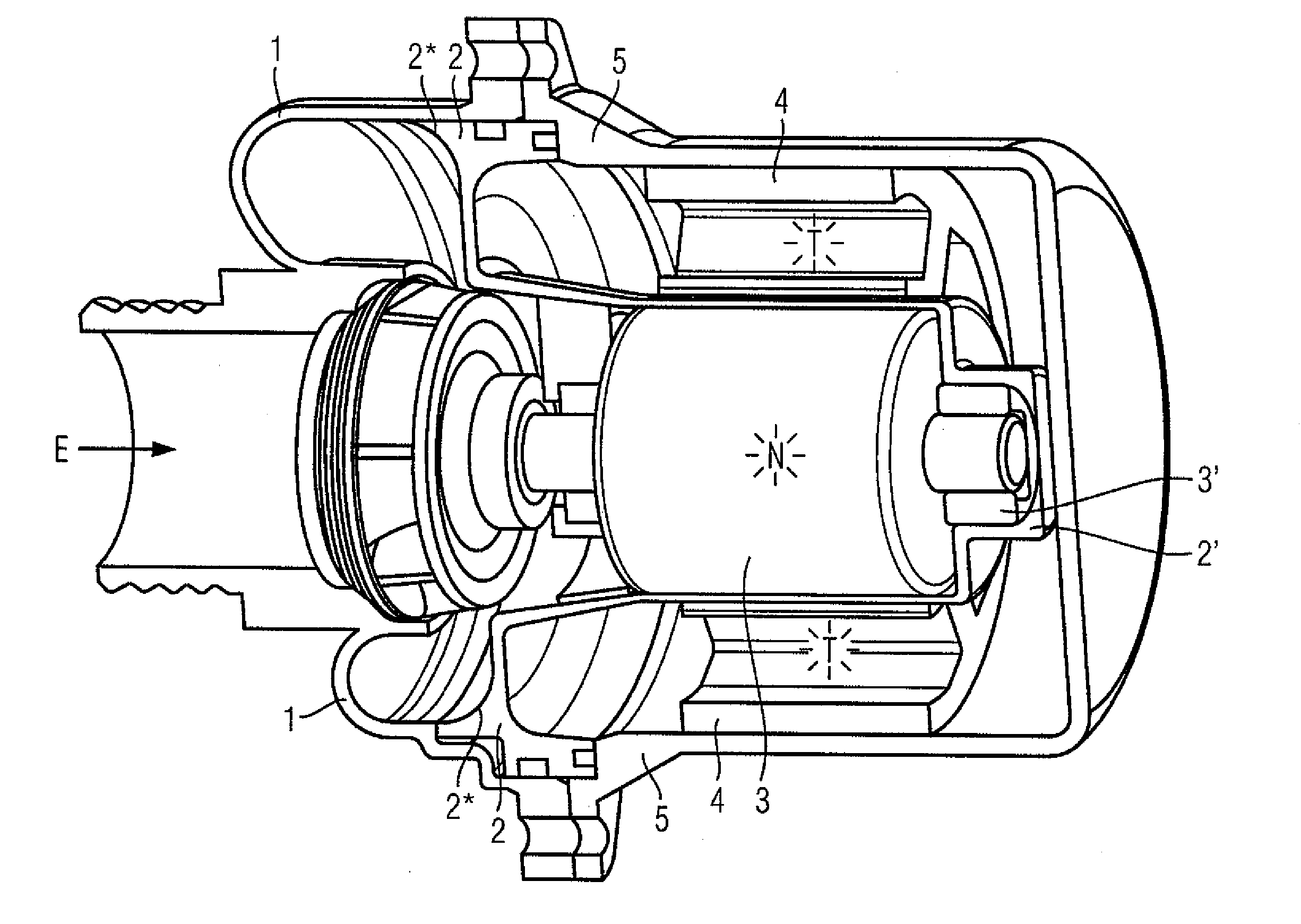
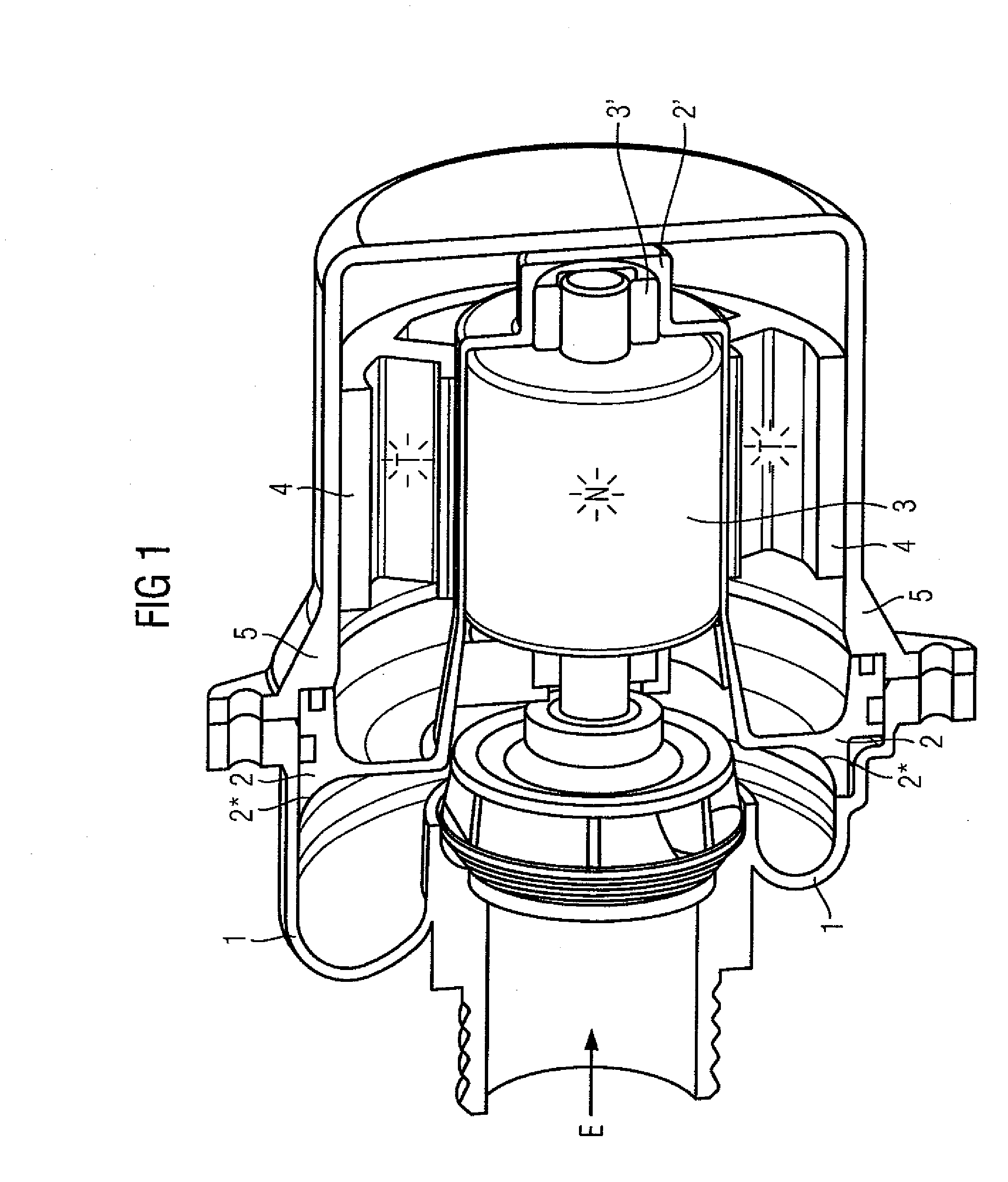
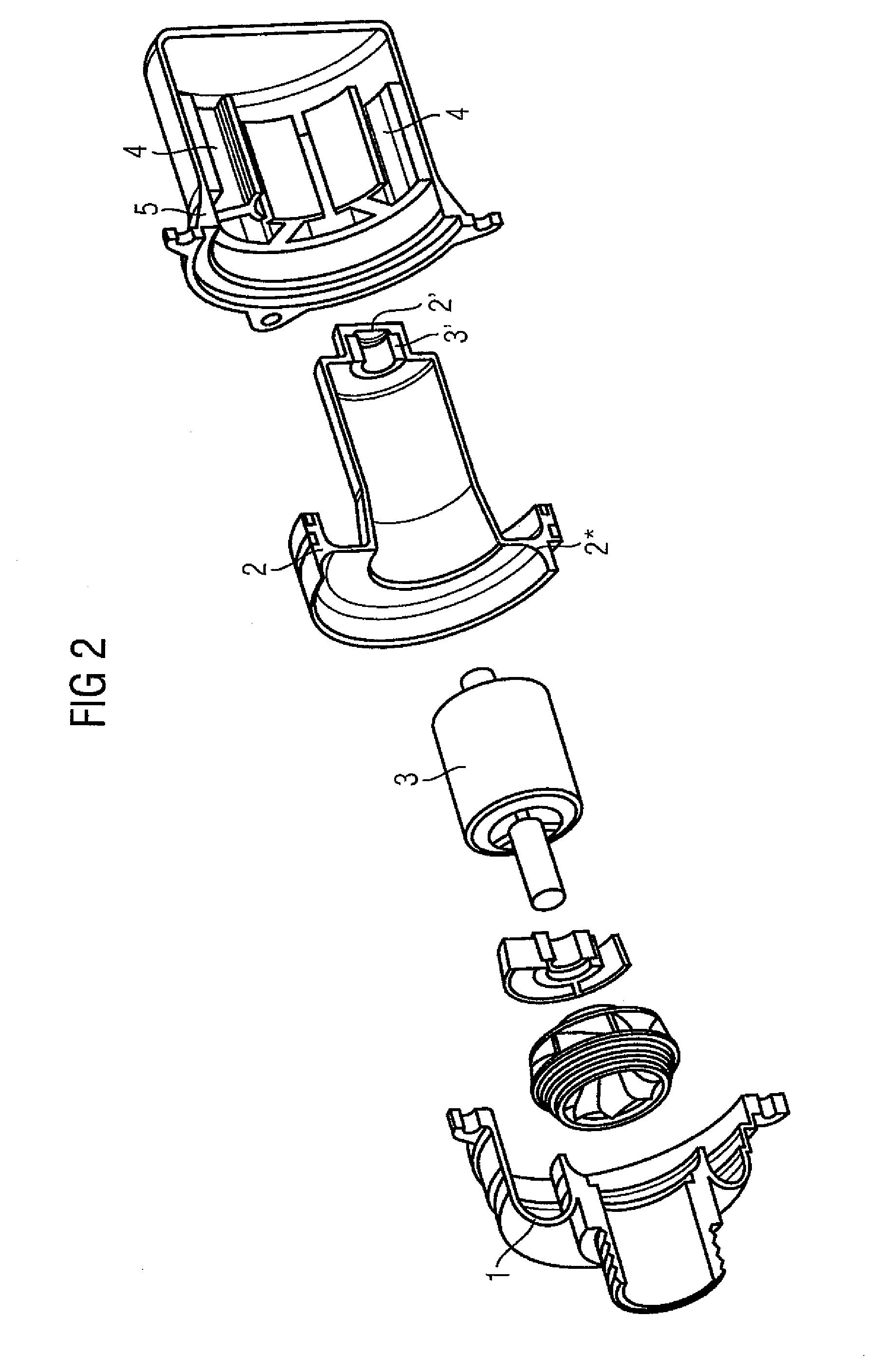
[0014]FIG. 1 is a centrifugal pump in longitudinal section. It comprises a spiral housing, which comprises a first housing part 1 and a second housing part 2. A central area of the second housing part 2 is of a continuous cup-shaped design to accommodate the rotor 3 situated in a wet chamber N. In the cup-shaped base part 2′ the second housing part 2 has a bearing 3′ for the rotatable mounting of the rotor 3. A stator 4 is arranged in a dry chamber T externally surrounding the second housing part 2 in the area of the rotor 3. The dry chamber T is sealed from the surroundings by a housing 5. The outer area of the second housing part 2 has an outline 2* of curved longitudinal section perpendicular to the direction of flow of the medium flowing in from the inlet E. The medium flowing in is represented by a bold arrow. The curved outline 2* serves to optimize the flow conditions inside the spiral housing. Any ingress of liquid or vapor from the wet chamber N into the dry chamber T is pr...


PUM


Abstract

A centrifugal pump includes a spiral housing with a first housing part and a second housing part. The central region of the second housing part is cup-shaped in order to receive the rotor situated in a wet chamber and forms a bearing at the base of the cup-shaped region rotatably mounting the rotor. A stator surrounds the second housing part and is situated in a dry chamber in the vicinity of the exterior of the rotor.

Description

PRIORITY CLAIM[0001]This is a U.S. national stage of application No. PCT / EP2008 / 051570, filed on Feb. 8, 2008, which claims Priority to the German Application No. 10 2007 010 050.9, filed: Mar. 1, 2007 the contents of both being incorporated herein by reference.BACKGROUND OF THE INVENTION[0002]1. Field of the Invention[0003]The invention relates to a centrifugal pump having a spiral housing. The invention further relates to the use of the centrifugal pump.[0004]2. Prior Art[0005]Centrifugal pumps having spiral housings are known. DE 103 47 302 A1 describes a two-part spiral housing for a centrifugal pump, which is of optimized design from the point of view of fluid mechanics. Such centrifugal pumps are generally driven by an electric motor, the stator of the electric motor being arranged in a dry chamber and the rotor in a wet chamber. The rotor therefore turns in the wet chamber, which is the medium to be pumped. The dry chamber and the wet chamber are divided by a separately arran...

Claims


Application Information

Patent Timeline
Patent Type & Authority Applications(United States)
IPC IPC(8): F04D29/44
CPCF04D13/0606F04D29/046F04D29/628F04D29/426F04D29/586F04D29/086
Inventor COLIC, RAJKO
Owner CONTINENTAL AUTOMOTIVE GMBH
Why Eureka
Try Eureka