
Blood platelet separation device

A separation device and platelet technology, applied in the direction of liquid separation, separation method, immiscible liquid separation, etc., can solve the problems of large loss, low purity, changing results, etc., and achieve large hysteresis, high separation efficiency, and flow fast effect

Active Publication Date: 2018-09-04
THE FIRST AFFILIATED HOSPITAL OF ZHENGZHOU UNIV
View PDF5 Cites 7 Cited by
  • Summary
  • Abstract
  • Description
  • Claims
  • Application Information

AI Technical Summary

Problems solved by technology

On the one hand, because the platelet layer is located in the middle of this method, the extraction is difficult, the loss rate is high, and the purity is low; on the other hand, the limited platelets in the whole blood will be more or less The blood cells stay in the plasma or permeate into the lower layer of blood cells. Under the premise of shortage of whole blood resources, it is necessary to purify the platelets in the plasma and blood cells many times, which makes the separation efficiency of blood cells low, cumbersome to operate, and the loss is large, which cannot meet the requirements. The increasing demand for the amount of platelets used in experiments; the practice of blindly increasing the centrifugation speed to obtain high-purity platelets during the centrifugation process is likely to cause the activation of platelets, because activated platelets can affect future experimental information and data, and even change the results, often with half the effort
There is still a certain amount of plasma protein in platelets separated by the above two methods. When performing fluorescence analysis or other analysis, the existence of plasma protein will have a certain interference effect on the experiment.

Method used


Image

  • Blood platelet separation device
  • Blood platelet separation device

Examples


Embodiment Construction

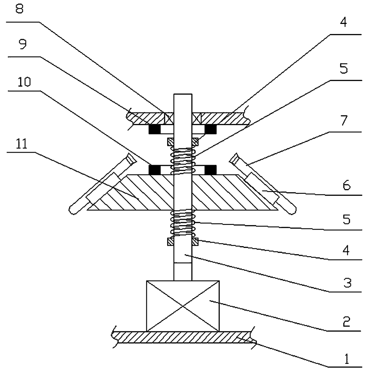
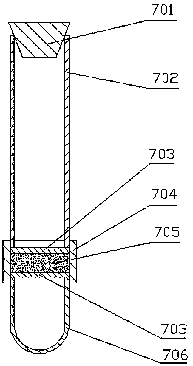
[0023] like figure 1 and figure 2 As shown, a platelet separation device of the present invention includes a housing 1 in which a motor 2 , a spline shaft 3 and a turntable 11 are arranged. The platelets are separated mainly through the centrifugation of the centrifuge tube 7 clamped on the turntable 11, and the initial stratification of the whole blood in the centrifuge test tube 7 is broken by the intermittent vibration of the turntable 11 on the spline shaft 3, so that the platelets can be continuously separated .

[0024] The motor 2 is fixedly arranged on the bottom wall of the housing 1, the output shaft of the motor 2 is arranged vertically and connected with the lower end of the spline shaft 3 through a continuously variable transmission, and the speed of the spline shaft 3 can be adjusted through the continuously variable transmission , and then adjust the centrifugal speed of the present invention. The upper end of the spline shaft 3 is connected to the top wall ...


PUM


Abstract

The invention relates to the field of medical instrument experiment equipment and in particular relates to a blood platelet separation device which comprises a shell, a motor, a spline shaft, a rotating disc and a vibration mechanism, wherein the motor is arranged inside the inner cavity of the shell; the spline shaft is connected with a motor output shaft; the rotating disc is mounted on the spline shaft in match; the vibration mechanism is used for controlling the rotating disc to vibrate intermittently in an axial direction of the spline shaft; the rotating disc takes the shape of a conicalplatform; a plurality of test tube clamps are arranged at intervals on the conical surface of the rotating disc; a centrifuge tube is fixedly arranged in any one test tube clamp; each centrifuge tubecomprises a fist tube body of which two ends are opened, and a second tube body of which one end is sealed and the other end is opened; one opened end of the first tube body is connected with the opened end of the second tube body through a connecting tube; a bovine serum agarose gel filtering layer is arranged inside the connecting tube; the other opened end of the first tube body is sealed through a test tube plug. The blood platelet separation device is high in separation efficiency, simple to operate and capable of thoroughly separating blood platelet from substances such as other blood cells and plasma proteins in whole blood.

Description

technical field [0001] The invention relates to the field of medical equipment and experimental equipment, in particular to a platelet separation device. Background technique [0002] Platelets are one of the formed components in mammalian blood, and are biologically active small pieces of cytoplasm that are lysed and shed from the cytoplasm of mature megakaryocytes in the bone marrow. Small in size, non-nuclear, irregular in shape, and 2-3 microns in diameter, platelets have long been regarded as non-functional cell fragments in the blood. [0003] With the advancement of clinical medicine and medical experimentation, more and more attention has been paid to the blood platelet component in whole blood, and the global clinical demand for platelets is increasing faster than that of red blood cells. This is mainly from the progress of clinical treatment methods. For example, radiotherapy and chemotherapy, bone marrow transplantation, massive blood transfusion, and heart tran...

Claims


Application Information

Patent Timeline
IPC IPC(8): B01D17/038B01D17/02
CPCB01D17/0202B01D17/0217
Inventor 薛瑞马胜利许晶晶韦娜郭思
Owner THE FIRST AFFILIATED HOSPITAL OF ZHENGZHOU UNIV
Learn More