Turbine blade having squealer

a turbine blade and squealer technology, which is applied in the direction of engine fuction, machine/engine, reaction engine, etc., can solve the problems and heating of the turbine blades and the turbine blades, so as to prevent the effect of reducing the thermal efficiency of the gas turbin

Active Publication Date: 2010-05-06
MITSUBISHI POWER LTD
View PDF11 Cites 40 Cited by
  • Summary
  • Abstract
  • Description
  • Claims
  • Application Information

AI Technical Summary

Benefits of technology

[0025]According to the present invention, since the damage of the squealer by a high-temperature combustion gas is prevented, and the loss of the combustion gas which flows over the turbine blade can be suppressed, a decrease in the thermal efficiency of a gas turbine can be prevented.

Problems solved by technology

In the gas turbine configured in this way, there is a possibility that the temperature of the combustion gas which acts on the plurality of stator vanes and turbine blades reaches 1500° C., and the stator vanes and the turbine blades are heated and damaged.
However, if the gap is too large, since a portion of the combustion gas flows over the blade tip and flows away to the downstream, energy loss occurs, which reduces the thermal efficiency of the gas turbine.
Additionally, although a portion of the combustion gas FG flows through the gap C between the ring segment 60 and the top surface 23a of the squealer 23, this gap flow causes the energy loss of the turbine, and causes a decrease in the thermal efficiency of the gas turbine.

Method used


Image

  • Turbine blade having squealer
  • Turbine blade having squealer
  • Turbine blade having squealer

Examples


first embodiment

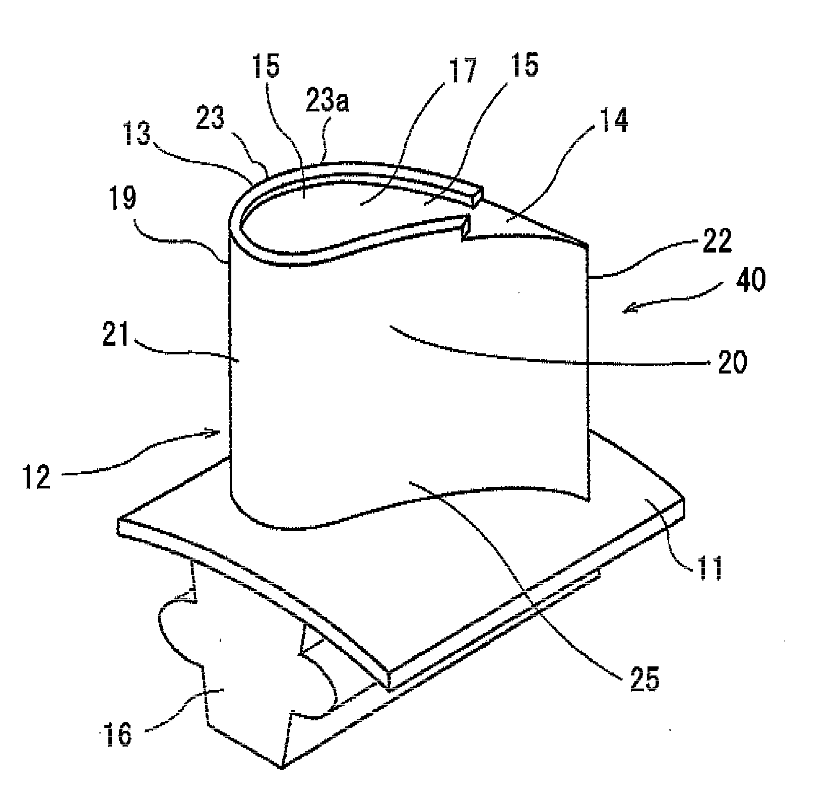
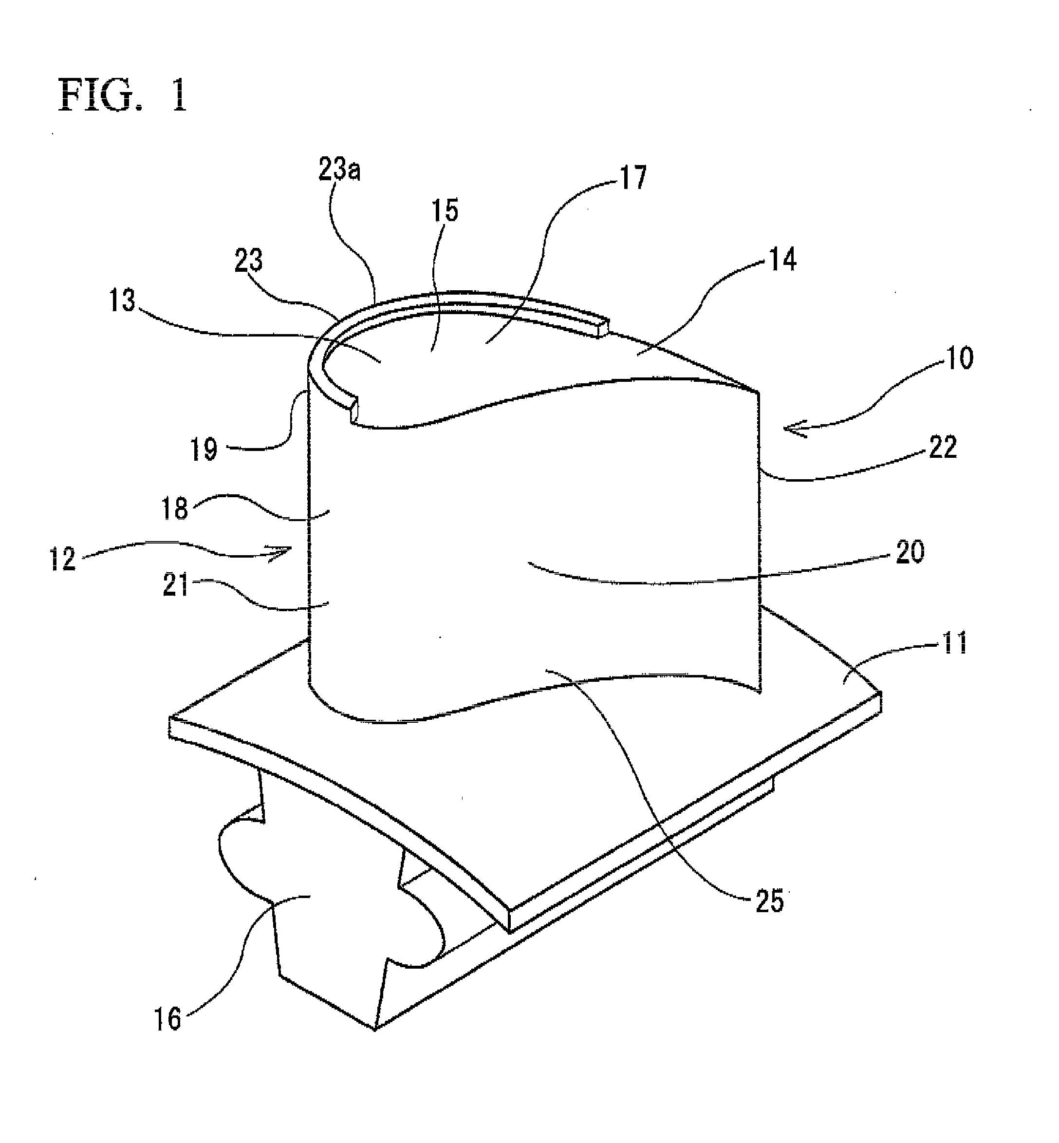
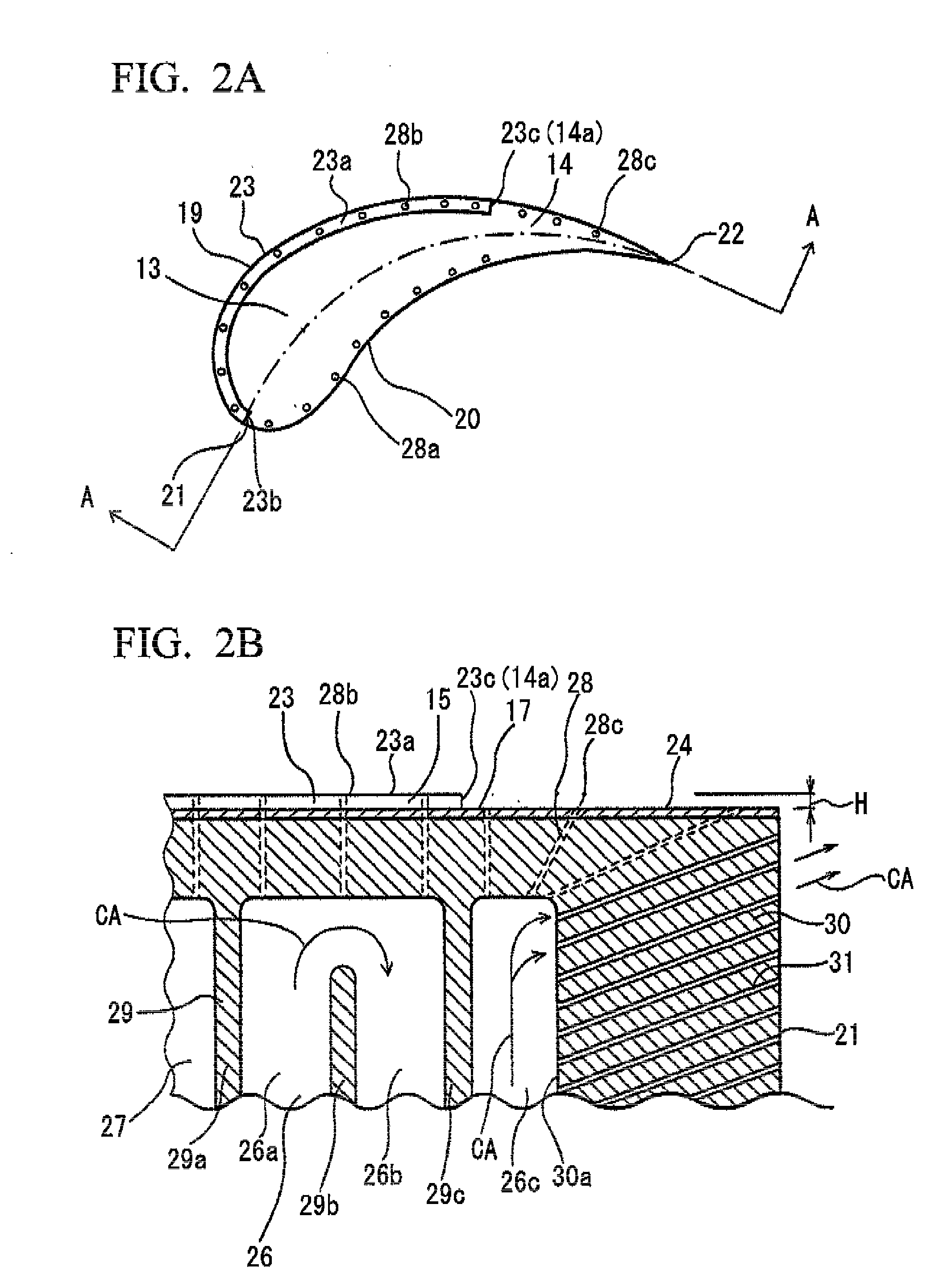
[0036]FIG. 1 shows a perspective view of a turbine blade FIG. 2A shows a schematic plan view of a blade tip of the turbine blade shown in FIG. 1, and FIG. 2B shows a portion of a cross-section (section A-A of FIG. 2A) in an erected direction of the turbine blade shown in FIG. 1. Common to individual constituent elements of a moving blade described in a conventional technique in terms of names or symbols will be described using the same names and symbols.

[0037]As shown in FIG. 1, the turbine blade 10 according to the first embodiment of the present invention is erected on a platform 11 embedded in a rotor disc (not shown) via a blade root portion 16, and a rotor (not shown) and the rotor disc rotate integrally. When the air foil 12 of the turbine blade 10 is seen from the radial direction of the rotor, a pressurized-surface-side blade wall 18 is concavely formed from a leading edge end 21 to a trailing edge end 22 on the upstream of the rotor in its rotational direction R, and a suc...

third embodiment

[0059]a turbine blade according to the present invention will be described with reference to FIGS. 4A and 4B.

[0060]As shown in FIGS. 4A and 4B, the first and second embodiments are the same in that the top plate 17 is formed by a smooth surface from the leading edge region 13 to the trailing edge region 14, and the blade tip 15 is blocked. Additionally, the first and second embodiments are the same in that the squealer 23 is provided along the suction-surface-side blade wall 19 and the pressurized-surface-side blade wall 20 from the leading edge region 13 to the trailing edge region 14, and the height of the upper surface 17t of the top plate 17 is set to be lower than the top surface 23a of the squealer 23 in order to reliably avoid any interference with the ring segment 60.

[0061]Meanwhile, a gas turbine may be operated in a state where the gap C between the lower surface of the ring segment 60 and the top surface 23a of the squealer 23 becomes small, and both surfaces come into co...


PUM


Abstract

A turbine blade of the invention includes an air foil including a plurality of cooling flow passages through which a cooling medium flows from a leading edge region to a trailing edge region, a top plate which forms the apex of the air foil, has a heat-resistant coating applied on the upper surface thereof, and includes a plurality of cooling holes, and a squealer which protrudes radially outward from the blade from the top plate, and is formed so as to extend from a leading edge end to a starting end of the trailing edge region along a suction-surface-side blade wall in a peripheral direction of the blade.

Description

TECHNICAL FIELD [0001]The present invention relates to a turbine blade having a squealer at a blade tip thereof.BACKGROUND ART [0002]A gas turbine is constituted by a compressor, a combustor, and a turbine. The air taken in from an air inlet is compressed by the compressor, and is supplied to the combustor as a high-temperature and, high-pressure compressed air. In the combustor the compressed air and fuel are mixed and combusted, and the result is supplied to the turbine as a high-temperature and high-pressure combustion gas. In the turbine, a plurality of stator vanes and turbine blades are alternately disposed within a casing, the turbine blades are rotationally driven by the combustion gas supplied to an exhaust passage, and the rotational driving is recovered as electric power by a generator coupled with a rotor. The combustion gas which has driven the turbine is converted into hydrostatic pressure by a diffuser, and is emitted to the atmosphere.[0003]In the gas turbine configu...

Claims


Application Information

Patent Timeline
Patent Type & Authority Applications(United States)
IPC IPC(8): F01D5/18
CPCF01D5/20F05D2240/307F05D2260/20
Inventor HADA, SATOSHI
Owner MITSUBISHI POWER LTD
Why Eureka
Try Eureka