Thermal Flow Meter

a flow meter and thermoplastic technology, applied in the direction of speed/acceleration/shock measurement, measurement devices, instruments, etc., can solve the problems of limited efficacy and excessive noise of prior art flow meters

Active Publication Date: 2010-05-13
FRESENIUS MEDICAL CARE HLDG INC
View PDF104 Cites 80 Cited by
  • Summary
  • Abstract
  • Description
  • Claims
  • Application Information

AI Technical Summary

Problems solved by technology

These aforementioned prior art flow meters often suffer from excessive noise and may have limited efficacy where space around the flowing fluid is limited (such as in conduits of small diameters).

Method used


Image

  • Thermal Flow Meter
  • Thermal Flow Meter
  • Thermal Flow Meter

Examples


Embodiment Construction

[0033]While the present invention may be embodied in many different forms, for the purpose of understanding of the principles of the invention, reference will now be made to the embodiments illustrated in the drawings and specific language will be used to describe the same. It will nevertheless be understood that no limitation of the scope of the invention is thereby intended. Any alterations and further modifications in the described embodiments, and any further applications of the principles of the invention as described herein are contemplated as would normally occur to one skilled in the art to which the invention relates.

[0034]“Treat,”“treatment,” and variations thereof refer to any reduction in the extent, frequency, or severity of one or more symptoms or signs associated with a condition.

[0035]“Duration” and variations thereof refer to the time course of a prescribed treatment, from initiation to conclusion, whether the treatment is concluded because the condition is resolved...


PUM


Abstract

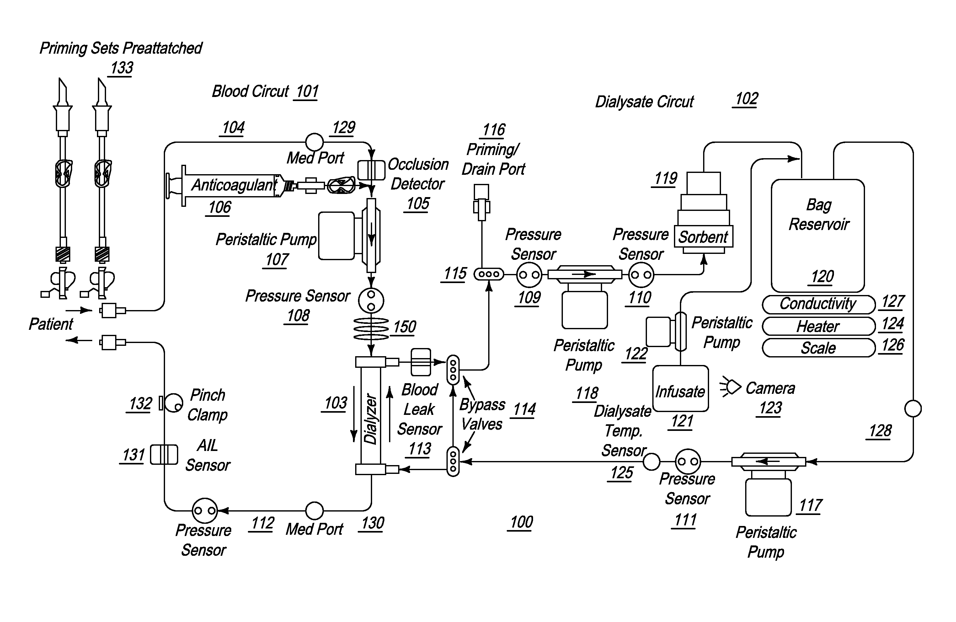
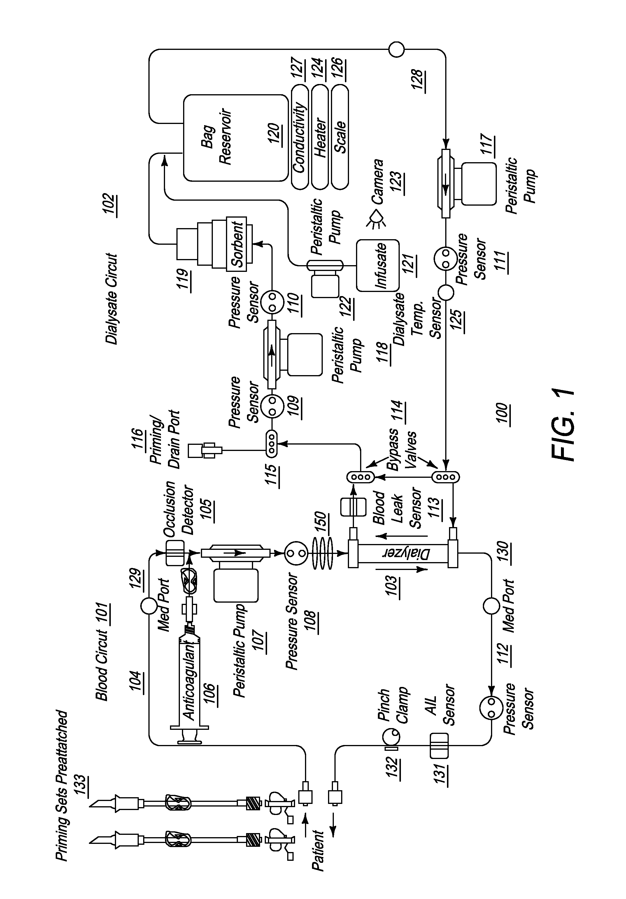
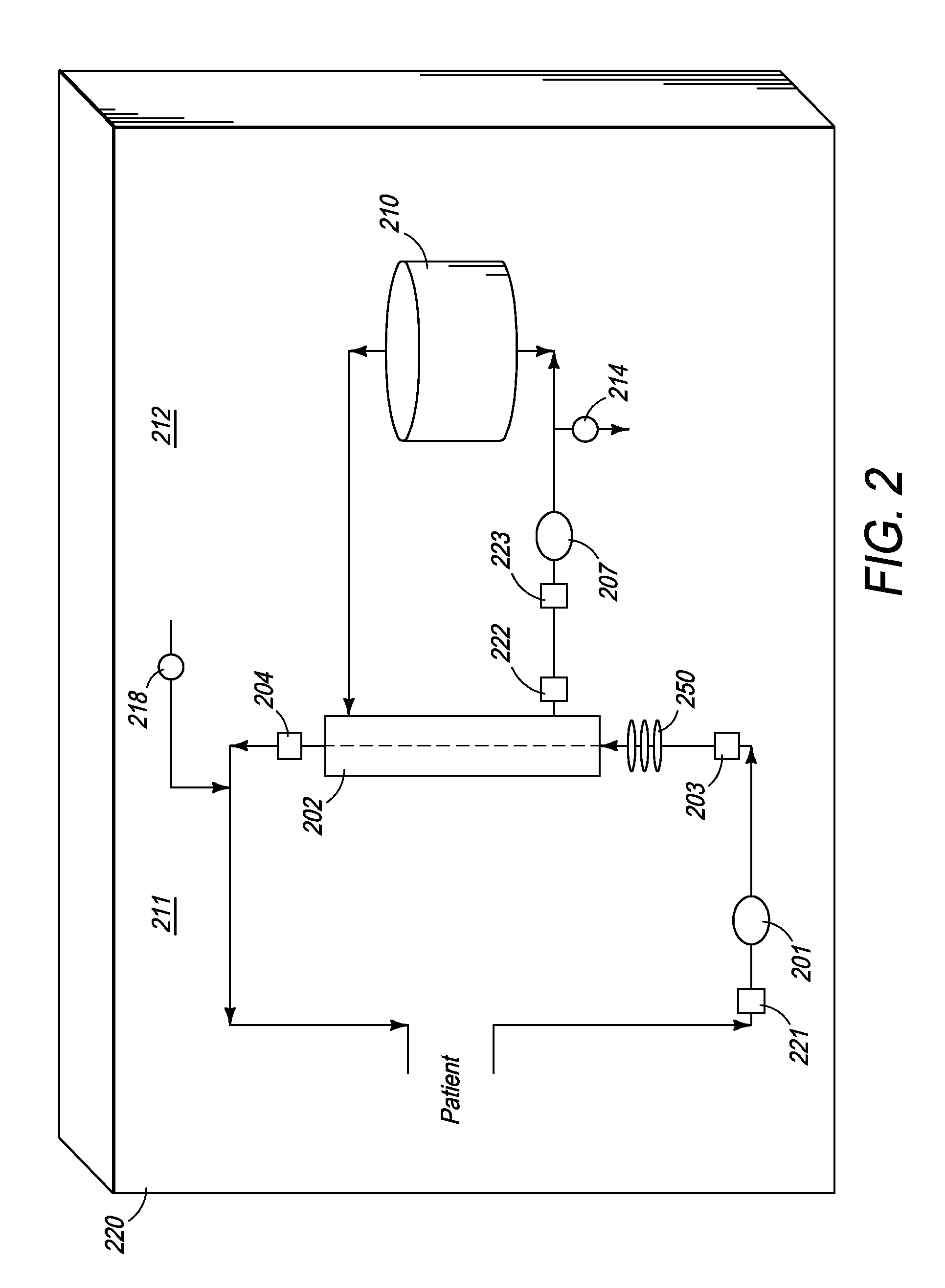
A thermal flow meter for use in dialysis is described, that uses a thermal wave to generate a signal in the fluid for which the flow rate is to be measured. The phase angle of the thermal wave signal changes when traversing downstream. The phase difference between the signals received downstream, compared with a reference excitation source signal is measured, and used to determine the flow rate of the fluid.

Description

CROSS-REFERENCE[0001]The present invention relies upon U.S. Patent Provisional Application No. 61 / 103,271, filed on Oct. 7, 2008, for priority and is a continuation-in-part of U.S. patent application Ser. No. 12 / 249,090, filed on Oct. 10, 2008 and which relies on U.S. Patent Provisional Application No. 60 / 979,113, filed on Oct. 11, 2007, for priority. All of the aforementioned applications are herein incorporated by reference.FIELD OF THE INVENTION[0002]The present invention generally relates to the field of systems and methods for fluid flow rate measurement, and, more specifically, to a thermal fluid flow meter for use in a dialysis manifold system.BACKGROUND OF THE INVENTION[0003]Fluid flow meters operate based upon the principle that the propagation velocity of a wave in a fluid, as determined by measuring the phase shift of the signal, is indicative of the velocity of the fluid. U.S. Pat. No. 3,894,431 to Muston, et al discloses determining fluid flow rates “by transmitting ult...

Claims


Application Information

Patent Timeline
Patent Type & Authority Applications(United States)
IPC IPC(8): G01F1/68G01F1/7084
CPCA61M1/3663G01F1/667G01F1/6842G01F1/6986G01F1/699G01F1/7084A61M1/155A61M1/154A61M1/152A61M1/362264A61M1/15632A61M1/36225A61M1/1565A61M1/36222A61M1/362265A61M1/3401A61M1/1562A61M1/153A61M1/36224A61M1/362266
Inventor FULKERSON, BARRY NEILSMITH, MARK F.
Owner FRESENIUS MEDICAL CARE HLDG INC
Why Eureka
Try Eureka