Film deposition apparatus

a technology of film deposition apparatus and film, which is applied in the direction of chemical vapor deposition coating, coating, metallic material coating process, etc., can solve the problems of affecting the quality of film deposition,

Inactive Publication Date: 2010-05-13
TOKYO ELECTRON LTD
View PDF9 Cites 373 Cited by
  • Summary
  • Abstract
  • Description
  • Claims
  • Application Information

AI Technical Summary

Benefits of technology

[0017]The present invention may provide a film deposition apparatus that substantially elimina

Problems solved by technology

In this case, replacing reaction gases by using purge gas takes a long time and the number of cycles may reach several hundred.
This results in a problem of an extremely long process time.
Accordingly, the reaction gas ejected toward the work piece is drawn in from the evacuation openings as an upward flow so that particles in the chamber may be blown upward by the upward flow of the gases and fall on the wafers, leading to contamination of the wafers.
Accordingly, it is not possible to prevent the reaction gas at both sides of the purge gas nozzle from passing by only the air curtain action from the purge gas nozzle.
Hence, it is not possible to avoid the reaction gas being diffused in the air curtain from an upstream side in the rotational direction.
Because of this, this structure cannot be app

Method used


Image

  • Film deposition apparatus
  • Film deposition apparatus
  • Film deposition apparatus

Examples


first embodiment

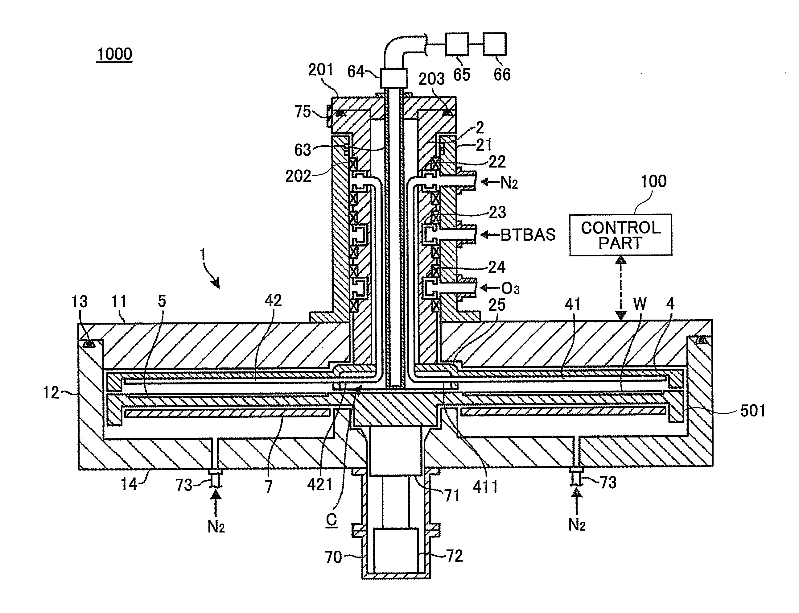
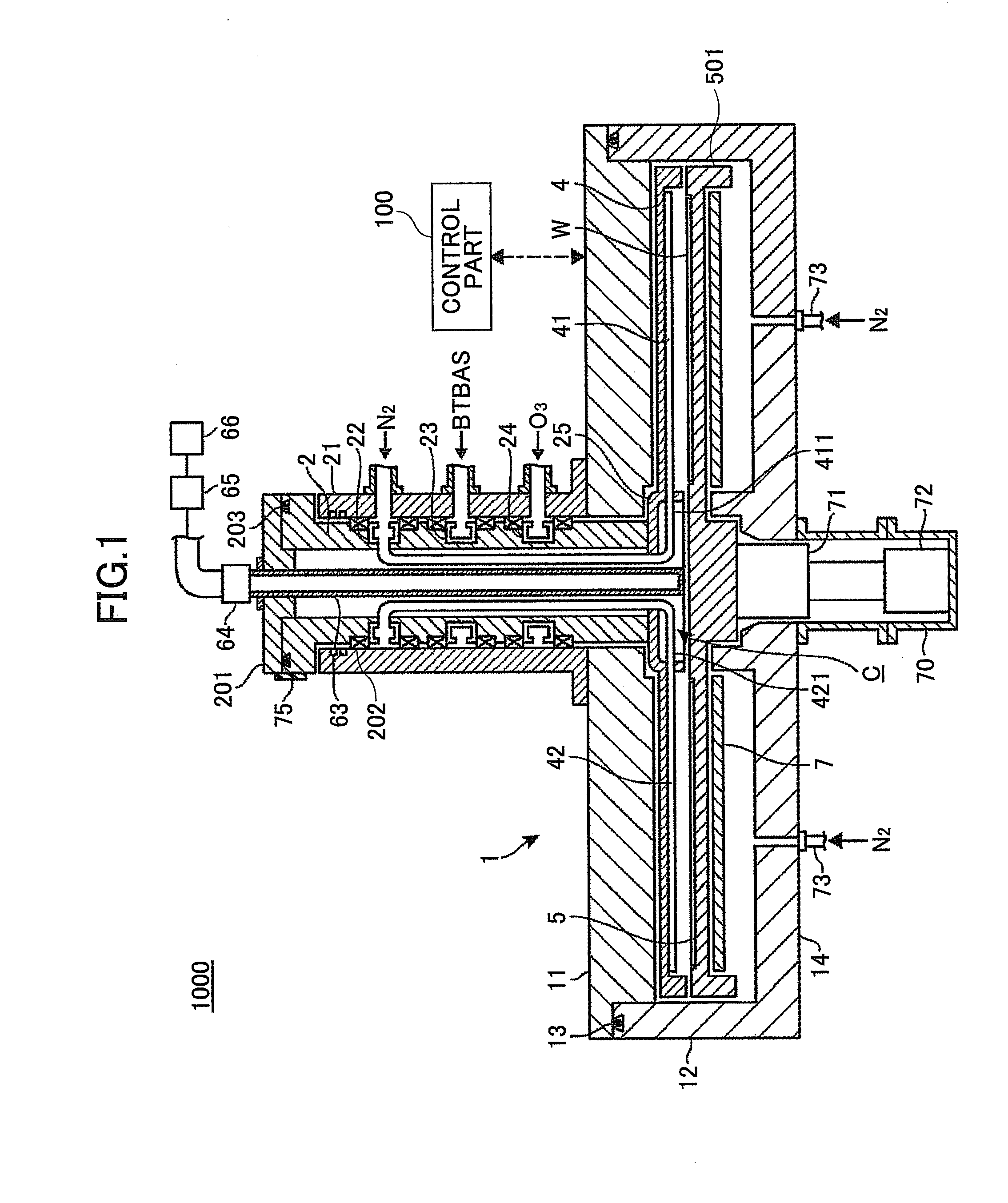
[0041]Referring to FIG. 1, which is a cut-away diagram taken along I-I′ line in FIG. 2, a film deposition apparatus 1000 according to an embodiment of the present invention has a vacuum chamber 1 having a flattened cylinder shape, and a susceptor (pedestal) 5 that is located inside the vacuum chamber 1. The vacuum chamber 1 is made so that a ceiling plate 11 can be separated from a chamber body 12. The ceiling plate 11 is pressed onto the chamber body 12 by internal decompression via a ceiling member such as an O ring 13, so that the vacuum chamber 1 is hermetically sealed. On the other hand, the ceiling plate 11 can be raised by a driving mechanism (not shown) when the ceiling plate 11 has to be separated from the chamber body 12.

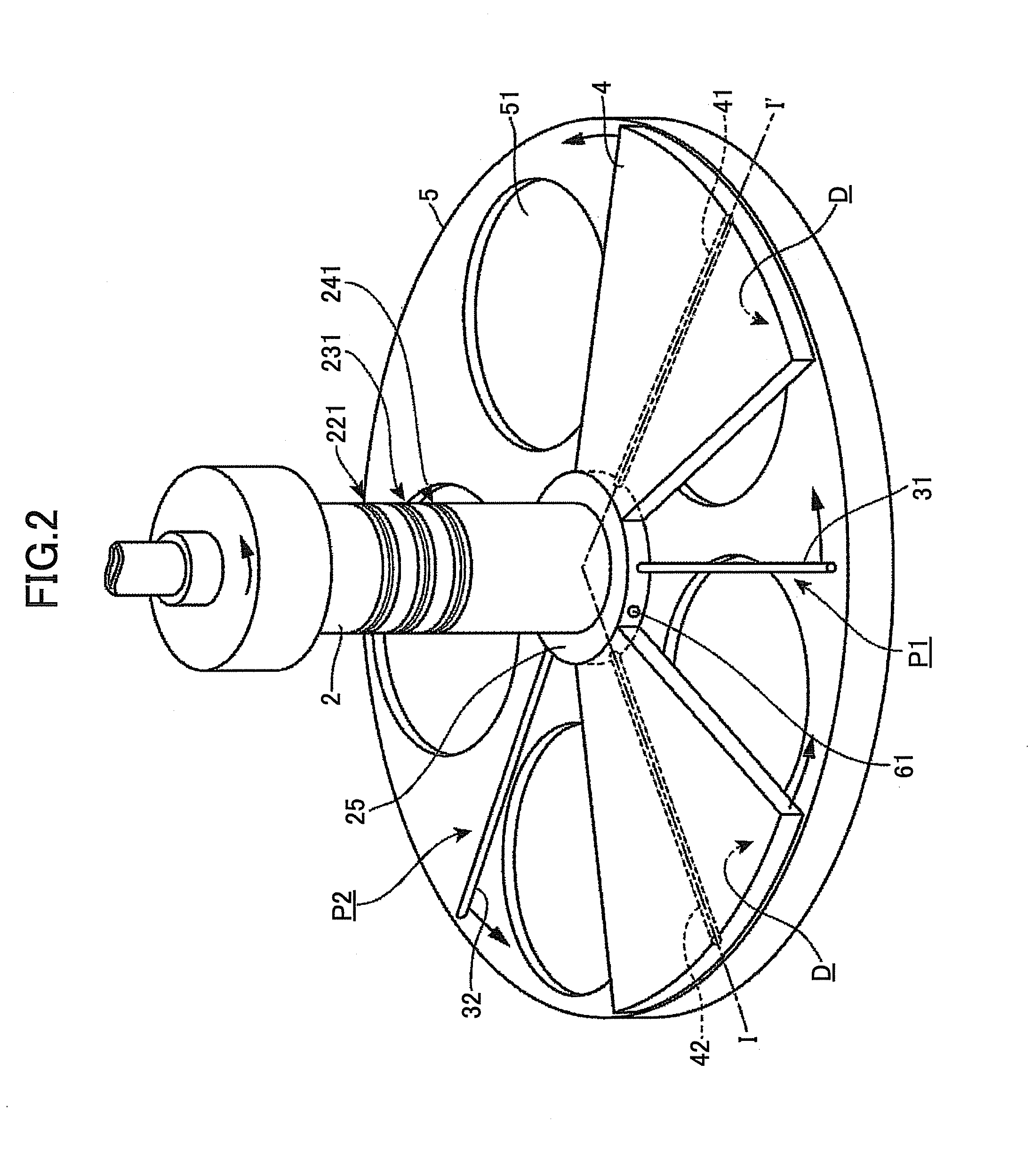
[0042]In this embodiment, the susceptor 5 is substantially a flat member having a top view shape of a circle. A center part located at a bottom surface of the susceptor 5 is fixed to a rotational shaft 71 extending in a vertical direction. In a case of tra...

second embodiment

[0091]Next, a film deposition apparatus 2000 according to a second embodiment of the present invention is described with reference to FIGS. 9 and 10. The second embodiment is different from the above-described embodiment in that various gases are supplied from the peripheral edges of the susceptor 5 to corresponding first reaction gas nozzle 31, second reaction gas nozzle 32 and the separation nozzles 41, 42 rather than supplying the gases from the center area of the susceptor 5. In the following embodiment, like components are denoted with like reference numerals as of the above-described embodiment and are not further explained.

[0092]As illustrated in FIGS. 9 and 10, the film deposition apparatus 2000 is different from the above-described deposition apparatus 1000 in that the rotational cylinder 2 is formed having an inner diameter matching the outer edge part of the susceptor 5, and the sidewall of the vacuum chamber (chamber body 12) of the rotational cylinder 2 is formed to ser...


PUM

PropertyMeasurementUnit
Sizeaaaaaaaaaa
Pressureaaaaaaaaaa
Areaaaaaaaaaaa

Abstract

A film deposition apparatus including a rotational member is rotated by a rotation mechanism around a vertical axis inside a chamber, a pedestal in the chamber and including substrate receiving areas formed along a circle having the vertical axis as a center, and first and second reaction gas supplying parts provided separately along a circumferential direction of the circle and supplying first and second reaction gases to the pedestal, a separating area in the rotational member and between first and second process areas to which first and second reaction gases are supplied, an evacuation port to evacuate an atmosphere inside the chamber, a separation gas supplying part in the separating area for supplying a separation gas, and an opposing surface part in the separating area on both sides of the separation gas supplying part and at a position forming a thin space between the opposing surface part and the pedestal.

Description

CROSS-REFERENCE TO RELATED APPLICATIONS[0001]This application is based upon and claims the benefit of priority of the prior Japanese Patent Application No. 2008-288124 filed on Nov. 10, 2008, the entire contents of which are incorporated herein by reference.BACKGROUND OF THE INVENTION[0002]1. Field of the Invention[0003]The present invention generally relates to a film deposition apparatus for depositing a film on a substrate by carrying out cycles of supplying in turn at least two source gases to the substrate in order to form one or more layers of a reaction product.[0004]2. Description of the Related Art[0005]As a film deposition technique in a semiconductor fabrication process, there is a technique in which a first reaction gas is adsorbed on a surface of a semiconductor wafer (referred to as a wafer hereinafter) under vacuum and then a second reaction gas is adsorbed on the surface of the wafer in order to form one or more atomic or molecular layers through reaction of the firs...

Claims


Application Information

Patent Timeline
IPC IPC(8): C23C16/00
CPCC23C16/45551C23C16/45578C23C16/4584C23C16/54H01L21/205
Inventor KATO, HITOSHI
Owner TOKYO ELECTRON LTD
Why Eureka
Try Eureka