Split Cycle Variable Capacity Rotary Spark Ignition Engine

Inactive Publication Date: 2010-05-13
SETH
View PDF28 Cites 12 Cited by
  • Summary
  • Abstract
  • Description
  • Claims
  • Application Information

AI Technical Summary

Benefits of technology

[0018]A still further object of the present invention is to provide a split cycle rotary spark ignition engine in which the first rotary configuration experiences only the hot combustion-expansion and exhaust phases through its entire working volumes and the second rotary configuration experiences only the cold intake and compression phases through its entire working volumes. Hence, each of the rotary configurations expands uniformly irrespective of each

Problems solved by technology

Due to un-throttled intake system the intake chambers always intake full capacity of intake gases, and therefore, considering the insta

Method used


Image

  • Split Cycle Variable Capacity Rotary Spark Ignition Engine
  • Split Cycle Variable Capacity Rotary Spark Ignition Engine
  • Split Cycle Variable Capacity Rotary Spark Ignition Engine

Examples


Embodiment Construction

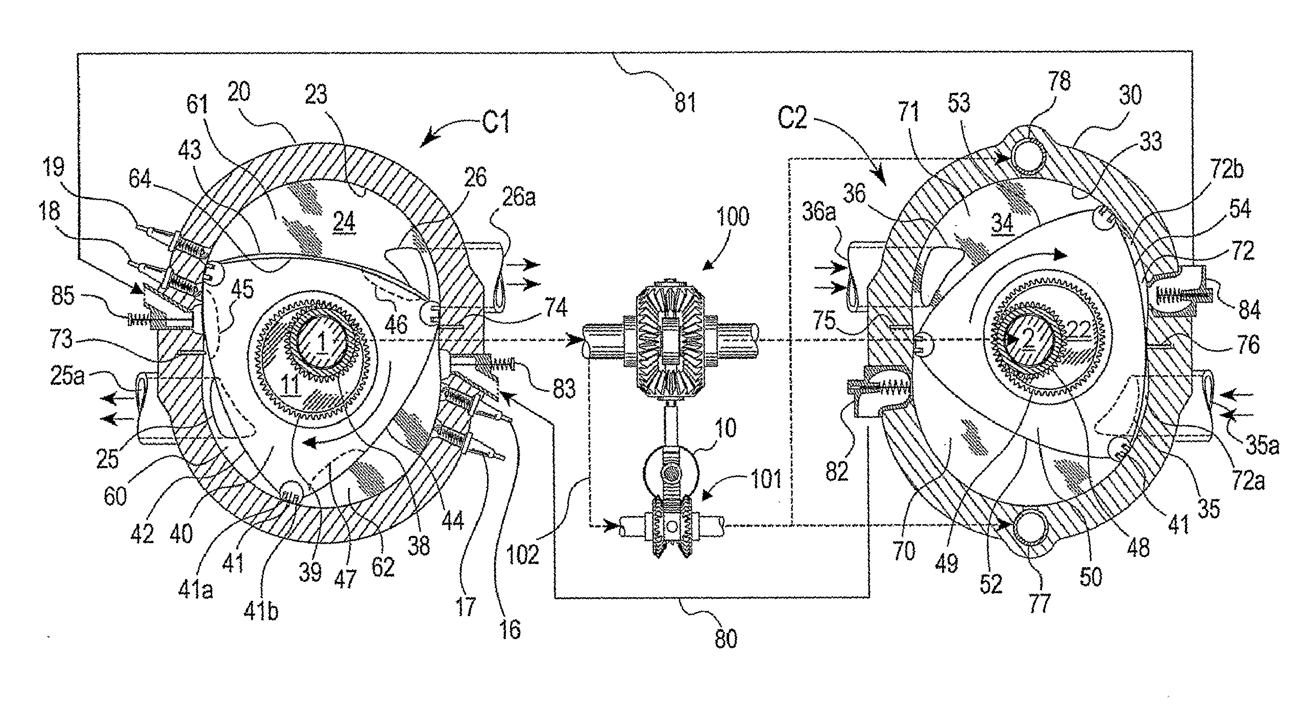
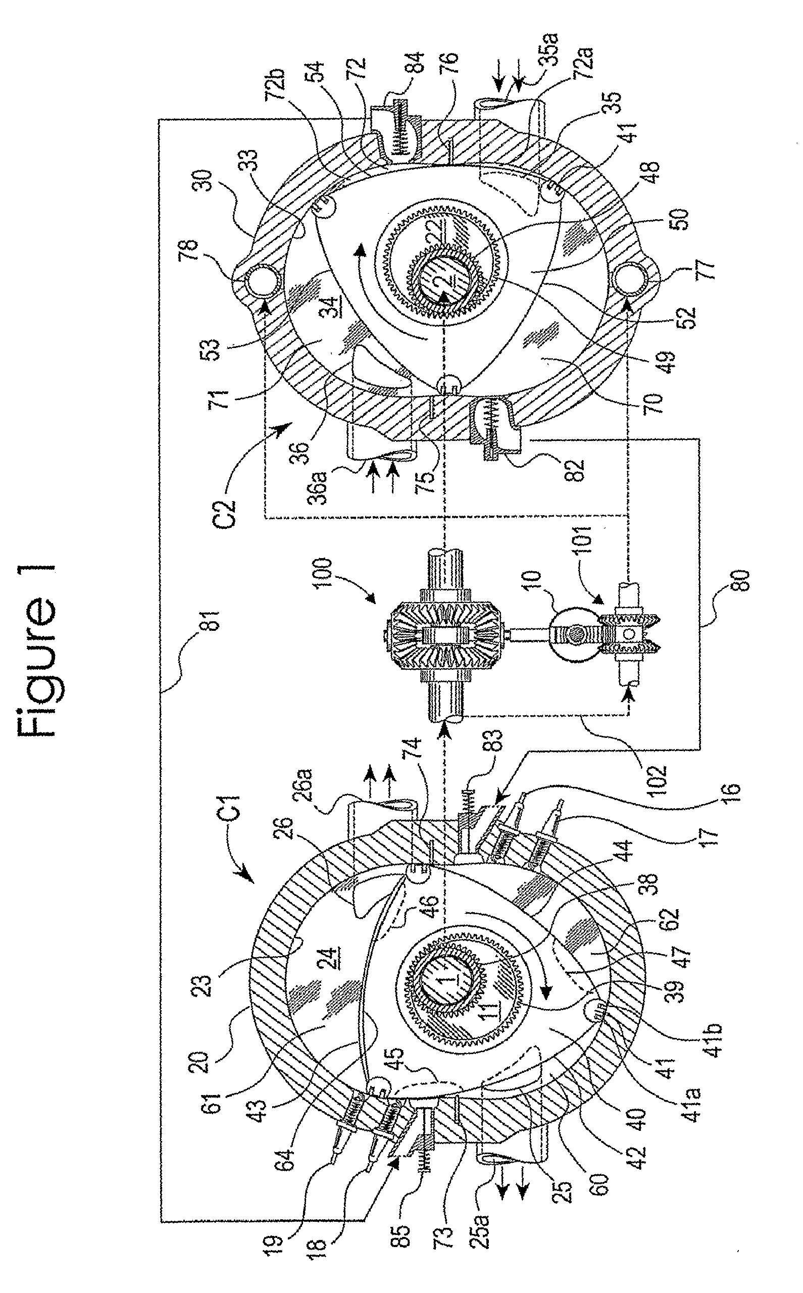
[0030]With reference first to FIG. 1, a split cycle rotary engine including a first rotary configuration C1 for carrying out the combustion-expansion and exhaust phases of four phase engine cycle and a second rotary configuration C2 for carrying out the intake and compression phases of four phase engine cycle (both in axial view). A first phase altering mechanism 100 operatively alters phase relation between said first rotary configuration C1 and second rotary configuration C2. The first rotary configuration C1 includes rotor housing 20 having an inner chamber defined by epitrochoidal peripheral wall 23 enclosed by two oppositely similar sidewalls 24 (only one is shown). The peripheral wall 23 is preferably a two-lobbed epitrochoid in which the lobes are joined each other by lobe junctions defining the minor axis regions of the said peripheral wall. Within the inner chamber a rotor 40 is rotatable about a lobe 11 eccentrically integrated with center shaft 1 which is rotatable about ...


PUM


Abstract

A split-cycle variable capacity rotary spark ignition engine system having at least a first rotary configuration (C1) including repetitively volume variable working chambers [60, 61, 62] for carrying out the combustion-expansion and exhaust phases and at least a second rotary configuration (C2) including repetitively volume variable working chambers (70, 71, 72) for carrying out the intake and compression phases of a four phase engine cycle. Dividing seal means (73, 74 of C1, 75, 76 of C2) for periodically dividing each of successive working chambers into a volume enlarging leading portion and a volume contracting trailing portion. Discharge valve means for varying compression chamber capacity through discharging fraction of trapped intake gas from compression chambers. A first phase altering arrangement is provided for varying the phase relation between the first rotary configuration (C1) and the second rotary configuration (C2). A second phase altering arrangement varies phase relation between the discharge valve means and corresponding compression chambers. The first rotary configuration (C1) having variable capacity combustion chambers operatively synchronize with the variable capacity compression chambers of the second rotary configuration (C2) so that accomplish nearly full-load-like combustion environment through a substantially wide engine operating range.

Description

FIELD OF THE INVENTION[0001]This invention relates to a spark ignition engine and more specifically to a split cycle rotary spark ignition engine. The present invention particularly relates to a split cycle variable capacity rotary spark ignition engine.BACKGROUND ART[0002]It is known that a spark ignition (SI) internal combustion (IC) engine is generally most efficient when the cylinder pressure and temperature at the end of a compression phase are closed to its maximum tolerable limit. In a conventional spark ignition engine, whether it is a rotary or a reciprocating one, this condition is achievable only when the throttle valve in the intake manifold is fully open to allow the maximum possible air or fuel-air mixture in the engine cylinder during intake phase and during following compression phase said intake air get compressed into a minimum chamber volume which is fixed by the design of the engine. During fully-open throttle condition the intake manifold pressure is near atmosp...

Claims


Application Information

Patent Timeline
IPC IPC(8): F02B53/06F02B53/12F02D41/04
CPCF01C1/22F01C11/004F01C20/02F02B53/00F02B55/14F02B53/04F02B53/02
Inventor MISTRY, JIBAN JYOTI
Owner SETH
Why Eureka
Try Eureka