
Controller and control method for internal combustion engine

Inactive Publication Date: 2010-05-13
TOYOTA JIDOSHA KK
View PDF11 Cites 2 Cited by
  • Summary
  • Abstract
  • Description
  • Claims
  • Application Information

AI Technical Summary

Benefits of technology

[0007]An object of the present invention is to provide a controller and a control method for an internal combustion engine that can control an output of internal combustion engine with high accuracy.

Problems solved by technology

This may possibly leads to hunting of throttle valve.

Method used


Image

  • Controller and control method for internal combustion engine
  • Controller and control method for internal combustion engine
  • Controller and control method for internal combustion engine

Examples


Embodiment Construction

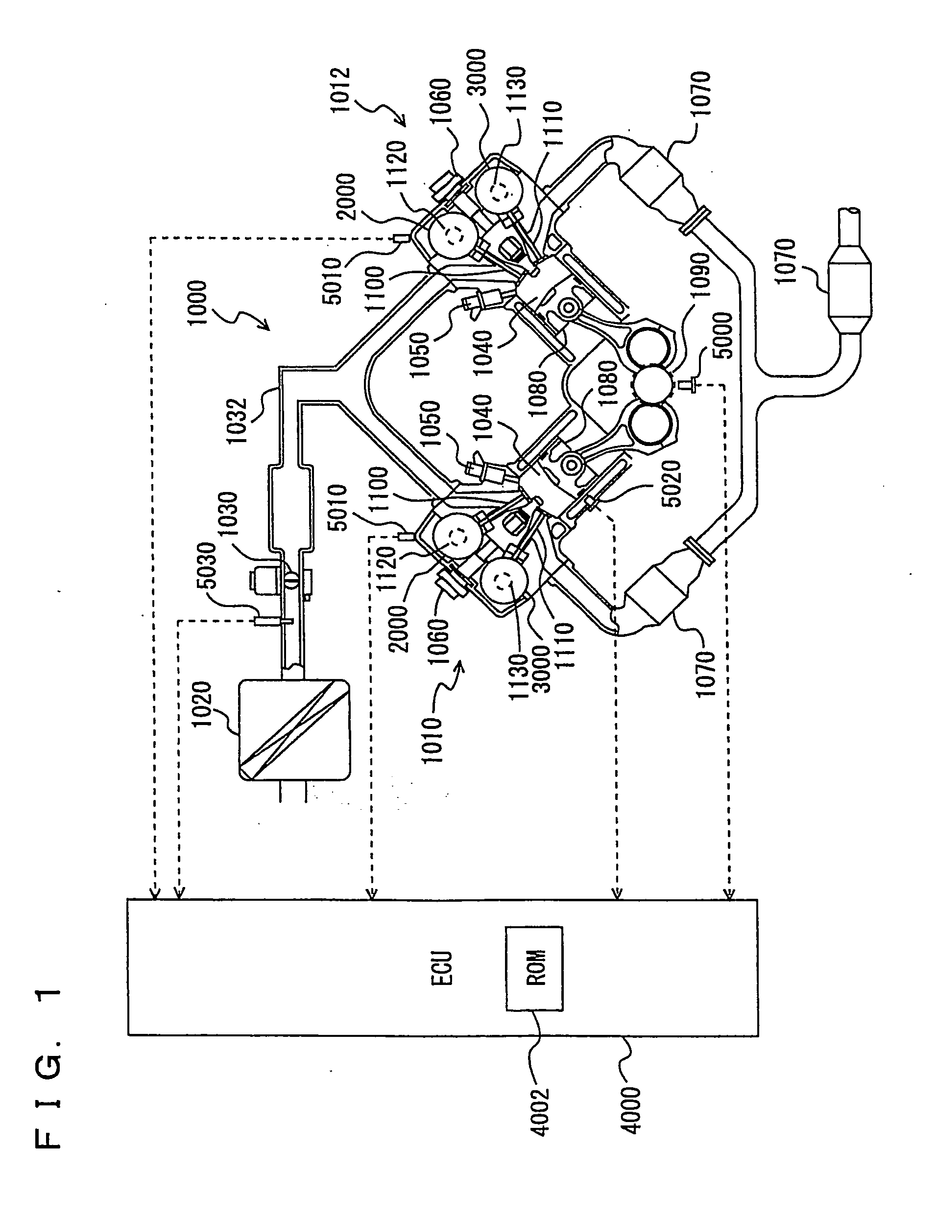
[0036]Referring to FIG. 1, an engine of a vehicle mounting the controller in accordance with an embodiment of the present invention will be described. The controller in accordance with the present embodiment is realized by an ECU (Electronic Control Unit) 4000 shown in FIG. 1, for example, executing a program stored in an ROM (Read Only Memory) 4002. ECU 4000 may be divided into a plurality of ECUs. Further, the program executed by ECU 4000 may be recorded on a recording medium such as a CD (Compact Disc) or a DVD (Digital Versatile Disc) and commercially distributed.

[0037]An engine 1000 is mounted as a driving source on the vehicle. Engine 1000 is a V-type 8-cylinder engine having an “A” bank 1010 and a “B” bank 1012 each including a group of four cylinders. Here, any engine other than the V8 engine may be used.

[0038]Into engine 1000, air is sucked from an air cleaner 1020. The quantity of sucked air is adjusted by a throttle valve 1030. Throttle valve 1030 is an electronic throttl...


PUM


Abstract

An ECU controls an adjusting mechanism adjusting an output of an engine, such as a throttle valve, a swirl control valve, an ignition plug, an intake valve, and an ACIS (Acoustic Control Induction System) changing the length of an intake manifold, in accordance with a ratio between a maximum value KL(MAX) of load factor and the load factor required of the engine by the driver and by the system mounted on the vehicle at current engine speed NE.

Description

TECHNICAL FIELD[0001]The present invention relates to a controller and a control method for an internal combustion engine and, more specifically, to a technique for controlling an adjustment mechanism that adjusts an output of the internal combustion engine.BACKGROUND ART [0002]Conventionally, in an internal combustion engine, an output is adjusted by adjusting quantity of intake air (amount of air filled in a cylinder), ignition timing and the like. By way of example, the output of internal combustion engine is adjusted by means of a throttle valve, a swirl control valve, an ignition plug, an intake valve, an exhaust valve, an ACIS (Acoustic Control Induction System) changing the length of an intake manifold and the like (hereinafter these mechanisms will also be referred to as adjusting mechanisms). The adjusting mechanism is controlled in accordance with an open position of an accelerator pedal (hereinafter also referred to as the accelerator position), which is operated by the d...

Claims


Application Information

Patent Timeline
IPC IPC(8): F02P5/00F02M35/10
CPCF02B31/085F02D11/105F02D13/0215F02D37/02F02D41/0002F02P5/1502Y02T10/146Y02T10/46Y02T10/42F02B27/0252F02B27/0294Y02T10/18Y02T10/12Y02T10/40
Inventor KAWAI, KATSUYUKIKAWAI, HIDEAKI
Owner TOYOTA JIDOSHA KK
Features
  • Generate Ideas
  • Intellectual Property
  • Life Sciences
  • Materials
  • Tech Scout
  • Unparalleled Data Quality
  • Higher Quality Content
  • 60% Fewer Hallucinations
Learn More