Motor controller system and method for maximizing energy savings

a technology of ac induction motor and ac induction motor, which is applied in the direction of general control strategies, motor/generator/converter stoppers, dynamo-electric converter control, etc., can solve the problems of inability of motor controllers, and achieve the effect of maximizing energy savings in ac induction motors

Active Publication Date: 2010-05-13
THE POWERWISE GRP INC
View PDF101 Cites 26 Cited by
  • Summary
  • Abstract
  • Description
  • Claims
  • Application Information

AI Technical Summary

Benefits of technology

[0006]The primary object of the present invention is to provide a system and method of maximizing energy savings in AC induction motors at every load.
[0007]Another object of the present invention is to provide a system and method which recognizes when a motor begins to slip and when the motor is about to stall.
[0012]The present invention fulfills the above and other objects by providing a motor controller system and method for maximizing the energy savings in the motor at every load wherein a motor is calibrated at one or more load points, establishing a control line or curve, which is then programmed into a non-volatile memory of the motor controller. A digital signal processor (DSP) a part of a closed loop architecture of the motor controller possesses the capability to observe the motor parameters such as current, phase angles and motor voltage. This DSP based motor controller is further capable of controlling the firing angle / duty cycle in open-loop mode as part of a semi-automatic calibration procedure. In normal operation, the DSP based motor controller performs closed-loop control to keep the motor running at a computed target control point, such that maximum energy savings are realized. The method described here works equally well for single phase and three phase motors.

Problems solved by technology

This meant that the control lines were horizontal and the motor controllers were not able to control the motor to specific calibrated operating point at every load to maximize energy savings.

Method used


Image

  • Motor controller system and method for maximizing energy savings
  • Motor controller system and method for maximizing energy savings
  • Motor controller system and method for maximizing energy savings

Examples


Embodiment Construction

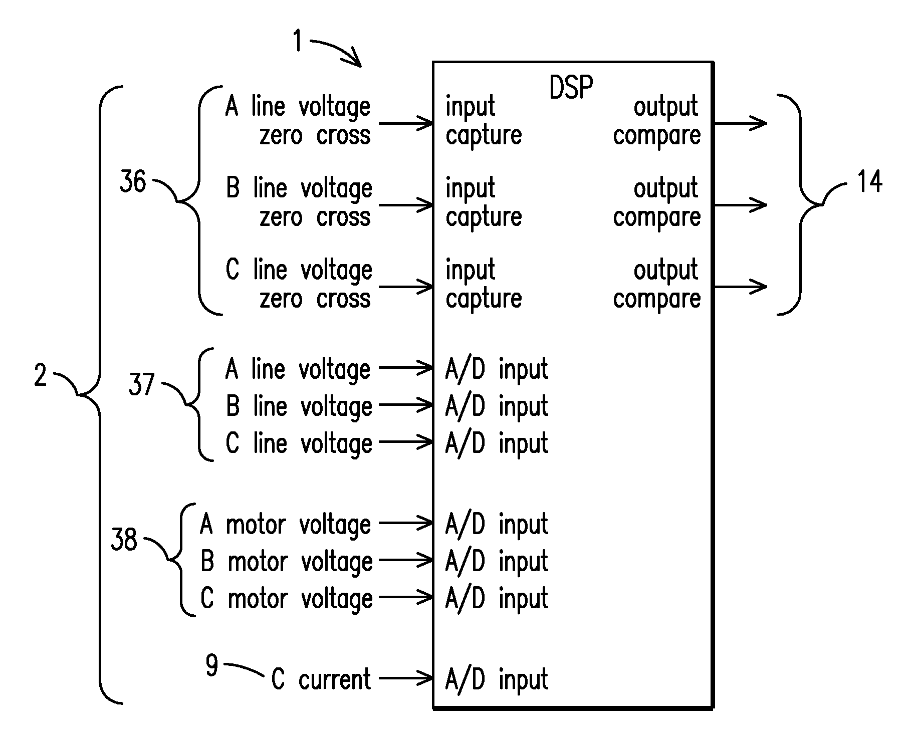
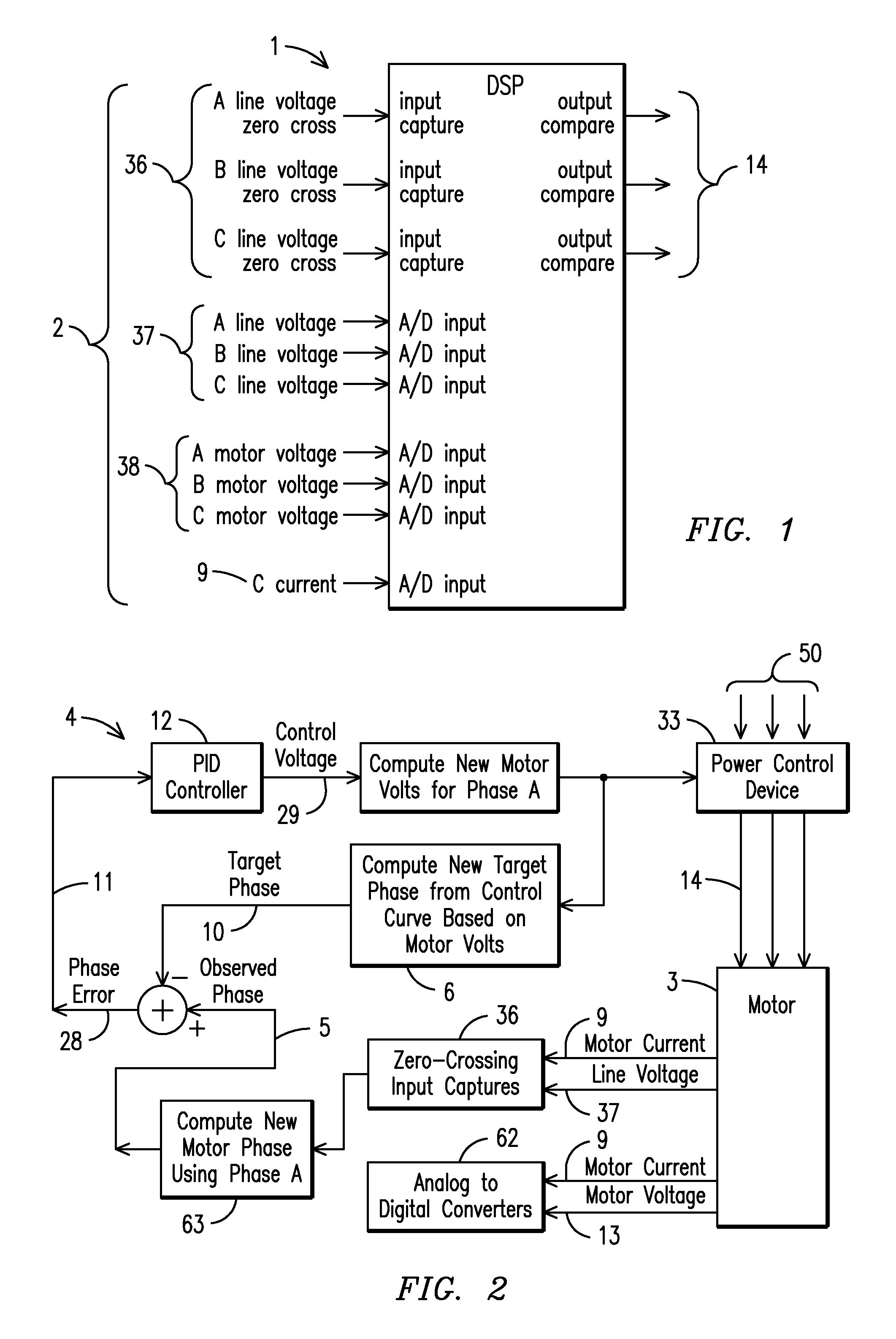
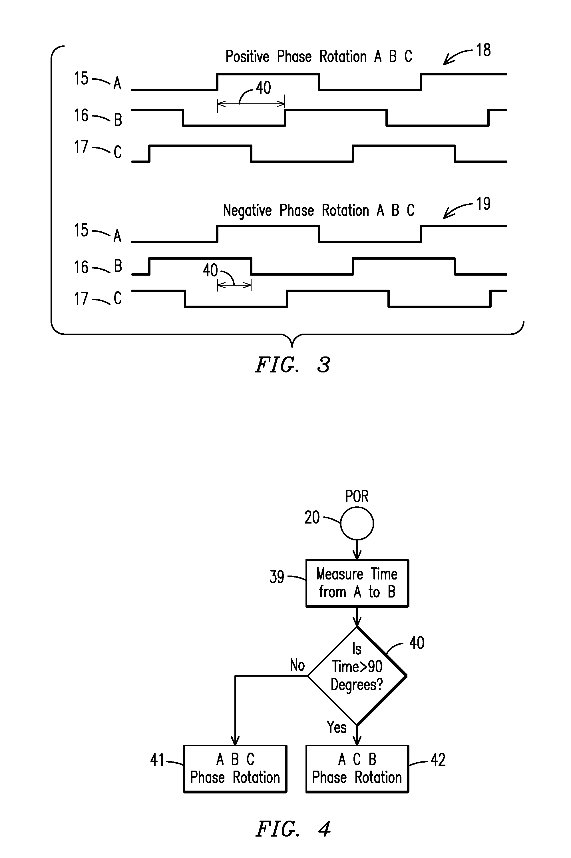
[0043]For purposes of describing the preferred embodiment, the terminology used in reference to the numbered components in the drawings is as follows:[0044]1. digital system processor (DSP)[0045]2. hardware inputs[0046]3. motor[0047]4. motor controller[0048]5. observed phase angle[0049]6. control line[0050]7. observed calibration data curve from sweep of control space[0051]8. supply divider resistors[0052]9. current[0053]10. target phase angle[0054]11. phase error signal[0055]12. proportional integral derivative (PID) controller[0056]13. root square mean (RMS) motor voltage[0057]14. power control device outputs[0058]15. phase A line voltage zero crossing[0059]16. phase B line voltage zero crossing[0060]17. phase C line voltage zero crossing[0061]18. positive phase rotation[0062]19. negative phase rotation[0063]20. power-on-reset (POR)[0064]21. stall point[0065]22. a,c,b phase turn on times[0066]23. firing angle / duty cycle[0067]24. percent load[0068]25. parametrical control line[0069...


PUM


Abstract

A motor controller (4) and method for maximizing the energy savings in an AC induction motor (3) at every load wherein the motor is calibrated at two or more load points to establish a control line (6), which is then programmed into a non-volatile memory (30) of the motor controller. A DSP-based closed-loop motor controller observes the motor parameters of the motor such as firing angle / duty cycles (23), voltage (37), current (9) and phase angles to arrive at a minimum voltage necessary to operate the motor at any load along the control line. The motor controller performs closed-loop control to keep the motor running at a computed target control point, such that maximum energy savings are realized by reducing voltage through pulse width modulation.

Description

CROSS REFERENCE TO RELATED APPLICATION[0001]This application claims the benefit of U.S. Provisional Application Nos. 60 / 933,706 filed Sep. 14, 2007; and 61 / 135,402 filed Jul. 21, 2008.BACKGROUND OF THE INVENTION[0002]This invention relates to a system and method for maximizing the energy savings in AC induction motors at every load, more particularly one that uses a digital signal processor that calibrates control lines to determine the most efficient operational characteristics of the motors.[0003]In prior systems and methods related to energy saving motor controllers using control lines of a motor, constant phase angle and / or constant power factor control were used to determine the control lines. This meant that the control lines were horizontal and the motor controllers were not able to control the motor to specific calibrated operating point at every load to maximize energy savings.[0004]Thus, a need exists for a method and system for AC induction motors which controls the motor...

Claims


Application Information

Patent Timeline
Patent Type & Authority Applications(United States)
IPC IPC(8): H02P4/00
CPCH02P6/002H02P6/182H02P23/0036H02P29/02H02P23/08H02P23/14H02P23/02H02P23/0004H02P6/28H02P23/26H02P23/0077H02P25/24
Inventor KELLEY, PAUL H.
Owner THE POWERWISE GRP INC
Why Eureka
Try Eureka