
Color processing apparatus, color processing method, and storage medium

Inactive Publication Date: 2010-05-13
CANON KK
View PDF4 Cites 49 Cited by
  • Summary
  • Abstract
  • Description
  • Claims
  • Application Information

AI Technical Summary

Problems solved by technology

However, both of the aforementioned conventional color matching and tone correction techniques have their respective advantages and disadvantages.
However, because color matching does not take into consideration the illuminance of lighting, the display luminance, or the like, it is not capable of matching the sense of tone or the sense of brightness among devices whose ranges of luminance differ greatly or among environments in which the illuminance differs greatly.
However, in tone correction, investigations into color gamut compression techniques, partial adaptation techniques, and the like has not made sufficient progress; therefore, not only do issues with respect to the faithful reproduction of the sense of chromaticity of colors remain, but there is also a problem in that tone correction processing is difficult to perform in real time in applications such as video display due to the high amount of processing.
In addition, because the conversion depends on the image structure, tone correction cannot be implemented as an LUT; therefore, the tone correction processing cannot be accelerated through approximation using interpolation computations, contrary to the color matching technique.
Furthermore, in cases such as where color gamut compression techniques are introduced into the tone correction, the processing is carried out on a pixel-by-pixel basis as a result, leading to the possibility of an extremely large increase in the processing cost.

Method used


Image

  • Color processing apparatus, color processing method, and storage medium
  • Color processing apparatus, color processing method, and storage medium
  • Color processing apparatus, color processing method, and storage medium

Examples


first embodiment

Apparatus Configuration

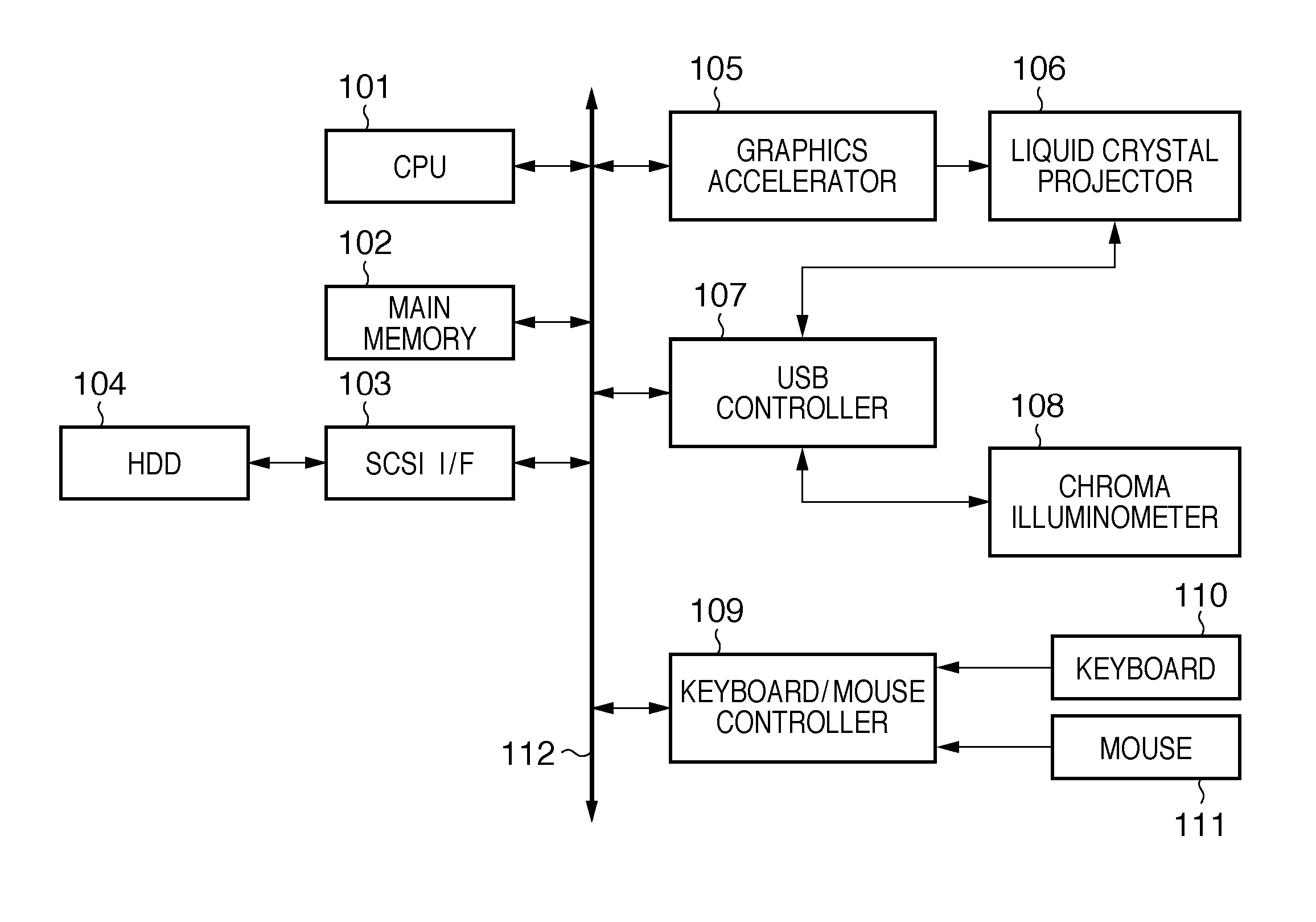
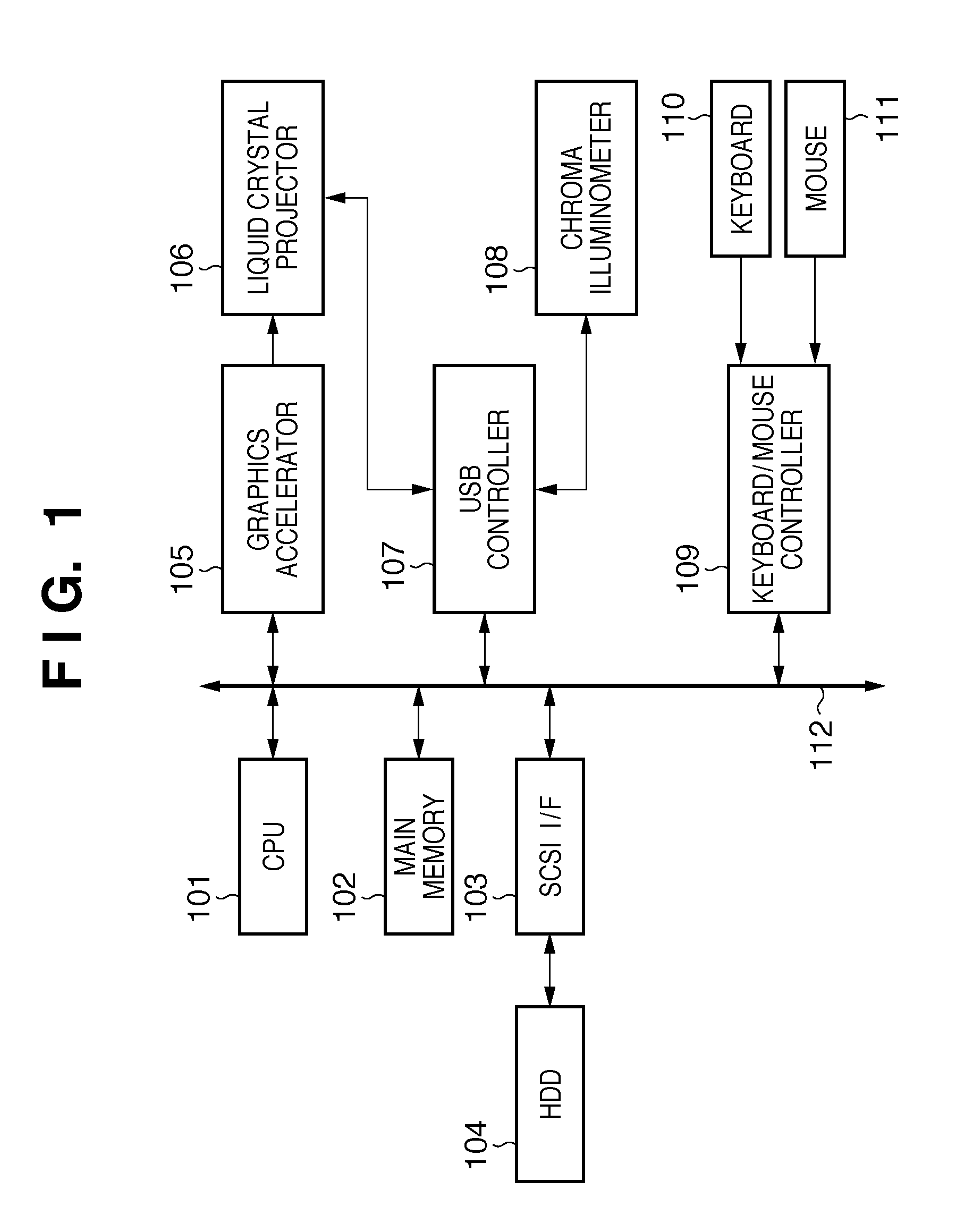
[0038]FIG. 1 is a block diagram illustrating the configuration of a color processing apparatus according to the present embodiment. The color processing apparatus illustrated in FIG. 1 according to the present embodiment is configured of what is known as a computer system, and image display software is executed thereby. The operations of this image display software shall be described hereinafter.

[0039]In FIG. 1, 101 represents a CPU that controls the overall processing of the apparatus, and 102 represents a main memory used as a work area of the CPU 101 and as a storage region. 104 represents a hard disk drive (HDD), which is connected to a PCI bus 112 via a SCSI I / F 103. Hereinafter, the hard disk drive, including an installed HD, shall be called an HDD 104. 105 is a graphics accelerator, which controls the projected images supplied to a liquid crystal projector 106. 108 is a chroma illuminometer, which obtains the illuminance and chromaticity of the ambient ...

second embodiment

[0108]Next, a second embodiment of the present invention shall be described.

[0109]The aforementioned first embodiment illustrated an example in which LUT descriptions can be applied to a Dst CAM profile. However, in a case such as where a color management application to which LUT descriptions cannot be applied has been introduced into the Dst CAM profile, it is not possible to apply the aforementioned first embodiment. Accordingly, by modifying the descriptions of the Dst device profile, the second embodiment makes it possible to obtain the same effects as the aforementioned first embodiment even in cases where LUT descriptions cannot be applied to the Dst CAM profile. Hereinafter, descriptions shall be provided particularly regarding the portions that differ from the first embodiment.

[0110]3D-LUT Generation Process

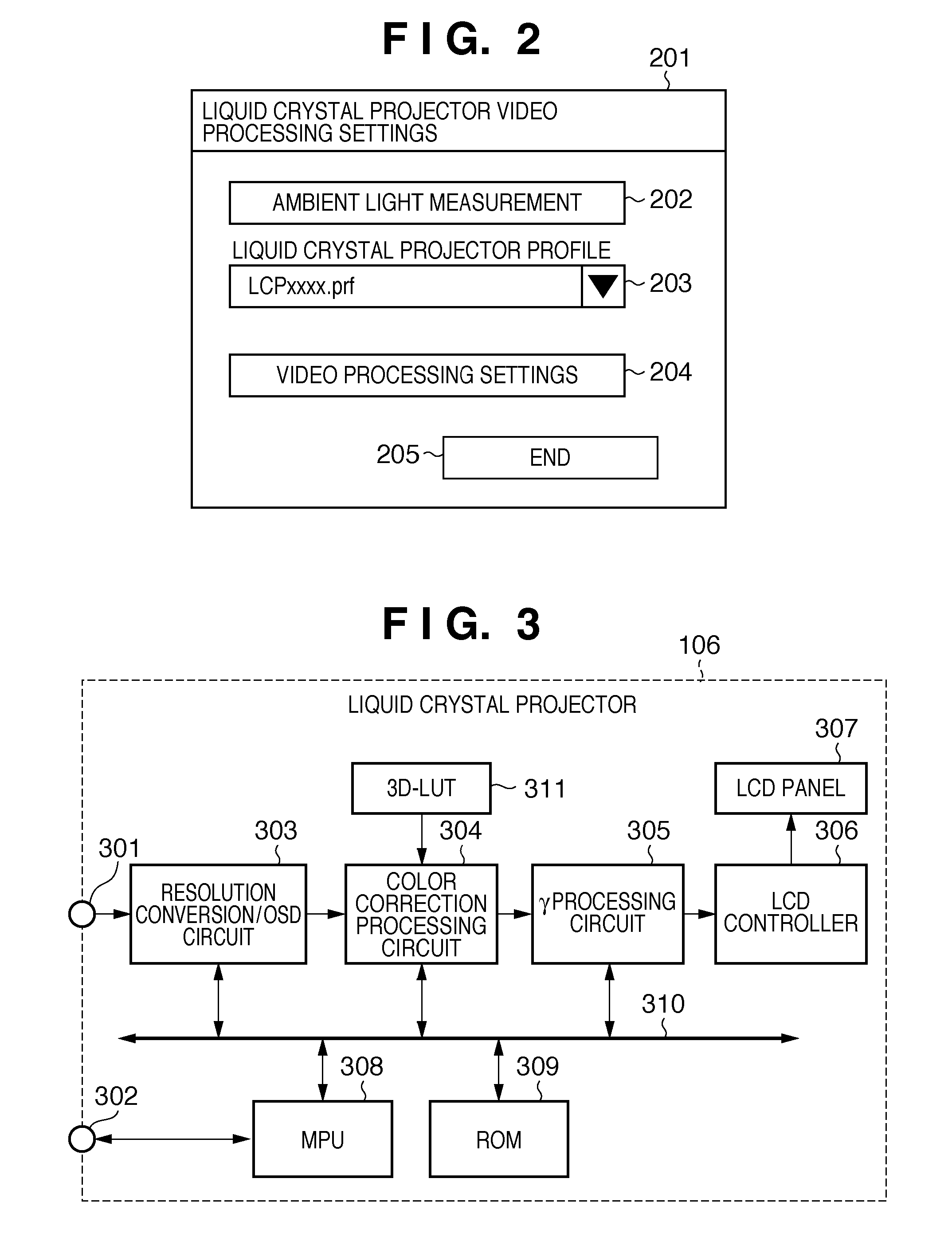
[0111]The process for generating the 3D-LUT 311 referenced by the color correction processing circuit 304 within the liquid crystal projector 106 in the second embodiment...

third embodiment

[0142]Next, a third embodiment of the present invention shall be described.

[0143]In the aforementioned first and second embodiments, an example was described in which color space coordinate value conversion is controlled by calculating an adaptive luminance based on the device white luminance and ambient light illuminance in the destination, thereby faithfully reproducing the appearance of an sRGB monitor in a liquid crystal projector. Conversely, the third embodiment aims to faithfully reproduce the appearance of a liquid crystal projector in an sRGB monitor. To achieve this, the color space coordinate value conversion based on device white luminance and ambient light illuminance described in the first and second embodiments as being performed in the destination is, in the third embodiment, applied to the source.

[0144]Apparatus Configuration

[0145]FIG. 16 is a block diagram illustrating the configuration of a color processing apparatus according to the third embodiment. The color pr...


PUM


Abstract

A color processing apparatus that creates a lookup table for performing a conversion process corresponding to ambient light comprises: an obtainment unit configured to obtain the illuminance of the ambient light and the device luminance of a destination device; a creation unit configured to create an adaptive luminance function from the illuminance of the ambient light and the device luminance; a setting unit configured to set an adaptive white luminance from a luminance value of grid point color data corresponding to a grid point in the lookup table, using the adaptive luminance function; a conversion unit configured to perform a conversion process on the grid point color data in accordance with a color appearance model, using the adaptive white luminance; and a saving unit configured to save the converted color data in the lookup table.

Description

BACKGROUND OF THE INVENTION[0001]1. Field of the Invention[0002]The present invention relates to a color processing apparatus, a color processing method, and a storage medium for reproducing an image in a device having a different range of luminance.[0003]2. Description of the Related Art[0004]Recent years have seen the dramatic advancement of image software technologies such as computer graphics (CG) technologies and display device technologies including high-luminance liquid crystal projectors, liquid crystal displays with broad color gamut compatible with Adobe color gamut, and so on. As a result of such advancement, it has become common to check digital images captured using a digital still camera (DSC) or digital images created through CG modeling on various types of display devices, such as displays, projectors, and the like.[0005]In order to check images in this manner, it is desirable for the appearance of the images to be uniform regardless of the type of display device. He...

Claims


Application Information

Patent Timeline
IPC IPC(8): G09G5/00G09G5/10
CPCG09G3/001G09G5/026G09G2320/0233G09G2320/0285G09G2360/16G09G2320/0673G09G2340/06G09G2360/144G09G2320/0666
Inventor MATSUOKA, HIROCHIKA
Owner CANON KK
Learn More