Light source device, lighting device and image display device

a technology of light source and image display, which is applied in the direction of instruments, projectors, optics, etc., can solve the problems of reducing the quality of a displayed image, affecting the quality of the displayed image, and causing speck noise in image display devices, etc., so as to achieve continuous reduction of speckle noise and low noise power consumption

Inactive Publication Date: 2010-05-13
PANASONIC CORP
View PDF11 Cites 25 Cited by
  • Summary
  • Abstract
  • Description
  • Claims
  • Application Information

AI Technical Summary

Benefits of technology

[0012]In the above light source device, noise and power consumption can be low and speckle noise c

Problems solved by technology

On the other hand, speckle noise is produced in image display devices, measuring instruments, exposure devices and lighting devices using laser light sources as light sources.
At this time, since the rays of light by way of different regions overlap on this screen in a complicated positional relationship and laser light has high coherency, the rays of light interfere with each other.
Since an interference pattern is formed by such interference, it reduces the quality of a displayed image as an unintended light intensity distribution (speckle noise).
Similarly, in the case of using a laser light source as a light source for a measuring instrument or an

Method used


Image

  • Light source device, lighting device and image display device
  • Light source device, lighting device and image display device
  • Light source device, lighting device and image display device

Examples


first embodiment

[0030]In this embodiment is illustrated a light source device which is commonly used in an image display device, a measuring device, an exposure device, a lighting device and the like and can reduce speckle noise which is problematic in these devices.

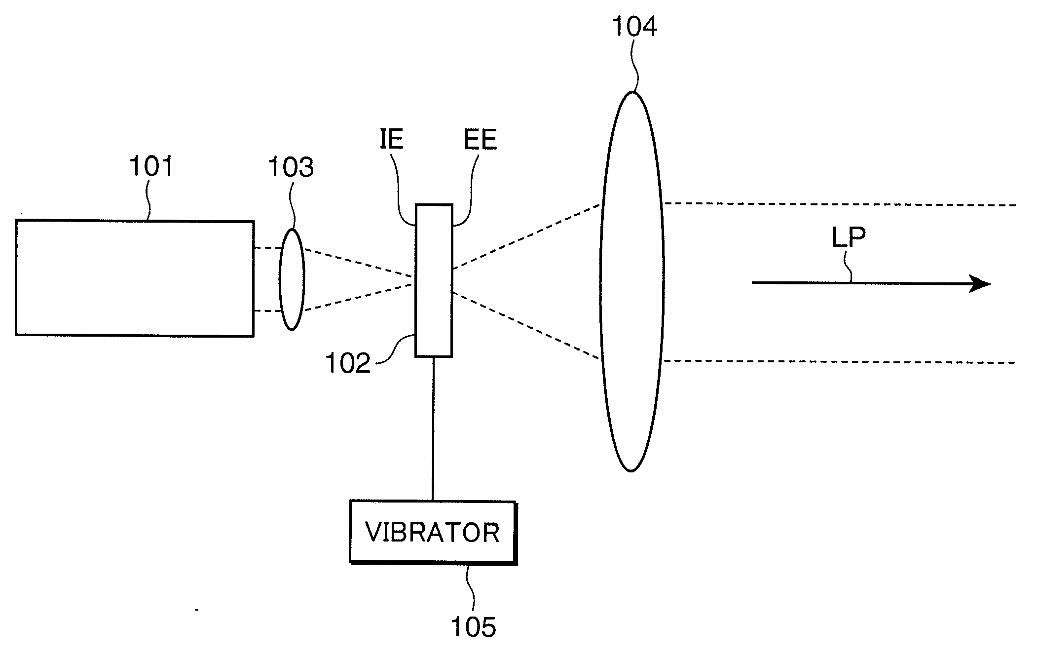
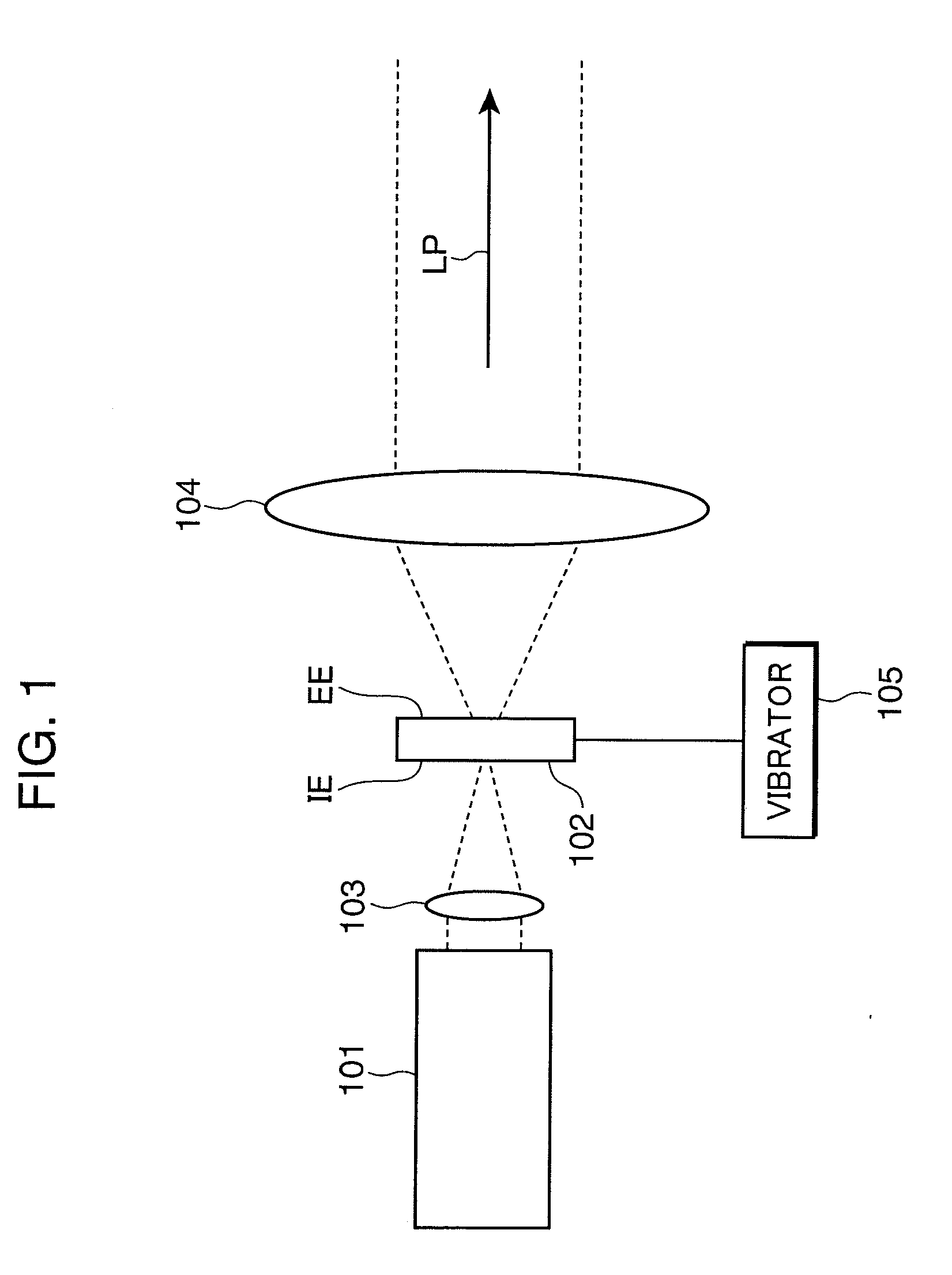
[0031]FIG. 1 is a conceptual diagram showing an exemplary construction of a light source device according to a first embodiment of the present invention. This light source device includes at least a laser light source 101 and a PR crystal 102 and, further includes a condenser lens 103, a field lens 104 and a vibrator 105 according to needs. After being condensed by the condenser lens 103, laser light (coherent light) emitted from the laser light source 101 is incident on the PR crystal 102 made of a material which exhibits a PR effect and a refractive index change of the laser light is induced by the PR effect of the PR crystal 102. By this refractive index change, an interference pattern of the laser light on an irradiated surface is c...

second embodiment

[0085]In this embodiment is illustrated a light source device which can be commonly used in an image display device, a measuring device, an exposure device, a lighting device and the like and can reduce speckle noise presenting a problem in these devices utilizing a thermal lens effect.

[0086]FIG. 8 is a conceptual diagram showing an exemplary construction of a light source device according to a second embodiment of the present invention. This light source device is at least provided with a laser light source 101a, a thermal lens crystal 501 which exhibits a thermal lens effect for laser light emitted from the laser light source 101a and having a specified wavelength, and a light guide 201. By causing laser light (coherent light) emitted from the laser light source 101a to be incident on the thermal lens crystal 501, a part of the laser light is absorbed in the thermal lens crystal 501 to induce a refractive index distribution due to a temperature gradient caused by generated heat. F...

third embodiment

[0103]In this embodiment is illustrated an image display device which reduces speckle noise. Although a light source device used in this embodiment is mainly used as a light source for the image display device, it is also applicable to a lighting device or the like.

[0104]FIG. 9 is a conceptual diagram showing an exemplary construction of an image display device according to a third embodiment of the present invention. As shown in FIG. 9, the image display device of this embodiment is provided with a plurality of laser light sources 301a, 301b and 301c, a plurality of dichroic mirrors 302a, 302b and 302c, a PR crystal 303, a light guide 304 and a spatial modulation element 305, wherein a light source device is constructed by the plurality of laser light sources 301a, 301b and 301c, the plurality of dichroic mirrors 302a, 302b and 302c, the PR crystal 303 and the light guide 304.

[0105]A case is described below where red (R), green (G) and blue (B) laser light sources capable of improv...


PUM


Abstract

A light source device is provided with a coherent light source for emitting the coherent light, and a pattern changer for changing an interference pattern of the coherent light on a surface of the illumination object. The pattern changer includes a photorefractive crystal which is arranged between the coherent light source and the illumination object and on an optical path of the coherent light and exhibits a photorefractive effect, and a changer for changing at least one of a light intensity distribution, a polarization direction, a wavelength and an intensity of coherent light incident on the photorefractive crystal. The illumination object is illuminated with the coherent light.

Description

FIELD OF THE INVENTION[0001]The present invention relates to a light source device, a lighting device and an image display device using coherent light such as laser light.DESCRIPTION OF THE BACKGROUND ART[0002]Coherent light sources (light sources for producing coherent light) such as laser light sources are used in image display devices, measuring instruments, exposure lithographic devices used for producing a circuit on a semiconductor substrate and the like. As compared with lamp light sources used in projectors and the like, laser light sources using lasers can more easily increase light utilization efficiency since having longer lives, higher emission efficiencies and stronger directionalities. In the case of being used in an image display device, a laser light source can display a sharp image with a large color reproduction region since being monochromatic.[0003]On the other hand, speckle noise is produced in image display devices, measuring instruments, exposure devices and l...

Claims


Application Information

Patent Timeline
IPC IPC(8): G02B27/20
CPCG02B27/48G03B21/2033G03B33/06G03B21/208G03B21/2053
Inventor KUSUKAME, KOICHIMIZUSHIMA, TETSUROYAMAMOTO, KAZUHISAFURUYA, HIROYUKIKADOWAKI, SHINICHIMIZUUCHI, KIMIDORO
Owner PANASONIC CORP
Why Eureka
Try Eureka