Method For Network Layer Handoff Over a Wireless LAN and an Associated Access Point Device

a wireless lan and access point technology, applied in the field can solve the problems of overlong latency, too high latency of network layer handoff to be used for voice communication, obvious voice quality degradation or even the occurrence of “call-drop”, etc., to achieve the effect of improving the handoff latency and avoiding random tests

Active Publication Date: 2010-05-13
IBM CORP
View PDF5 Cites 55 Cited by
  • Summary
  • Abstract
  • Description
  • Claims
  • Application Information

AI Technical Summary

Benefits of technology

[0015]Thus, the present invention achieves seamless network layer handoff by using a temporary IP address. However, in contrast to the approach proposed by Forte et al., the temporary IP address is not selected through multiple instances of tests carried out by the mobile node. Instead, an available IP address pool is maintained by the AP, and a temporary IP address is assigned by the AP to the mobile node for immediate use when a new IP address is needed. Random tests and additional waiting time for a response can be avoided, thus improving the handoff latency during IP address acquisition.

Problems solved by technology

In many cases, especially in applications that use voice communication over a WLAN, an overlong period of time for network handoff often leads to obvious voice quality degradation or even the occurrence of “call-drop”.
Therefore, network layer handoff has been too high in latency time to be used for voice communication over a WLAN.
However, due to the duplicate address detection process required by the DHCP server, multiple instances of message interaction are required in the IP address acquisition process.
Hence, the acquisition of a new IP address from the DHCP server leads to an overlong latency, generally on the order of seconds.
This is unacceptable for applications such as voice communication.
Such a test method is somewhat random and brings about an additional overhead of waiting during the timeout for the ARP response, more than about 100 ms, and thus cannot meet the strict latency requirement for voice transmission.

Method used


Image

  • Method For Network Layer Handoff Over a Wireless LAN and an Associated Access Point Device
  • Method For Network Layer Handoff Over a Wireless LAN and an Associated Access Point Device
  • Method For Network Layer Handoff Over a Wireless LAN and an Associated Access Point Device

Examples


Embodiment Construction

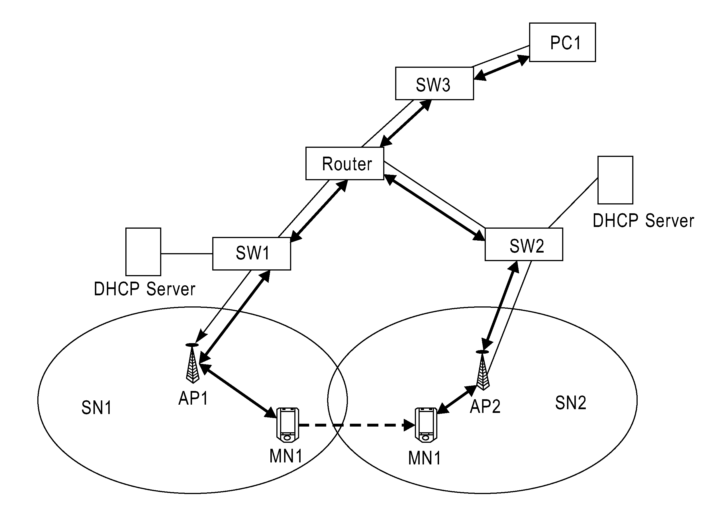
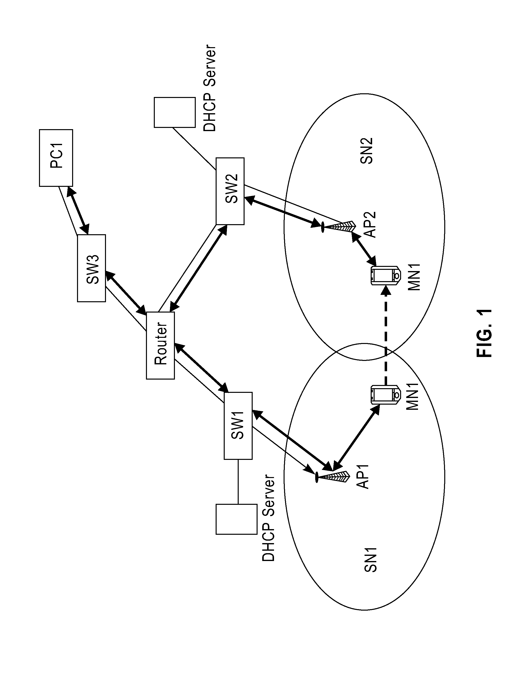
[0022]FIG. 1 shows a schematic diagram illustrating voice communications between mobile node MN1 and personal computer PC1. However, in practice, it is also possible to conceive other scenarios in which communication is done between mobile nodes or between a mobile node and fixed voice equipment. In the case shown in FIG. 1, a mobile node MN1 carries out bi-directional communication with PC1 via access point AP1, a switch and a router. When MN1 moves from the coverage area of access point AP1 to that of another access point, AP2, a handoff to AP2 is necessary for ensuring a seamless connection Since AP1 and AP2 shown in FIG. 1 are located in different subnets, a network layer handoff occurs, where MN1 has to be assigned a new IP address from the DHCP server associated with AP2.

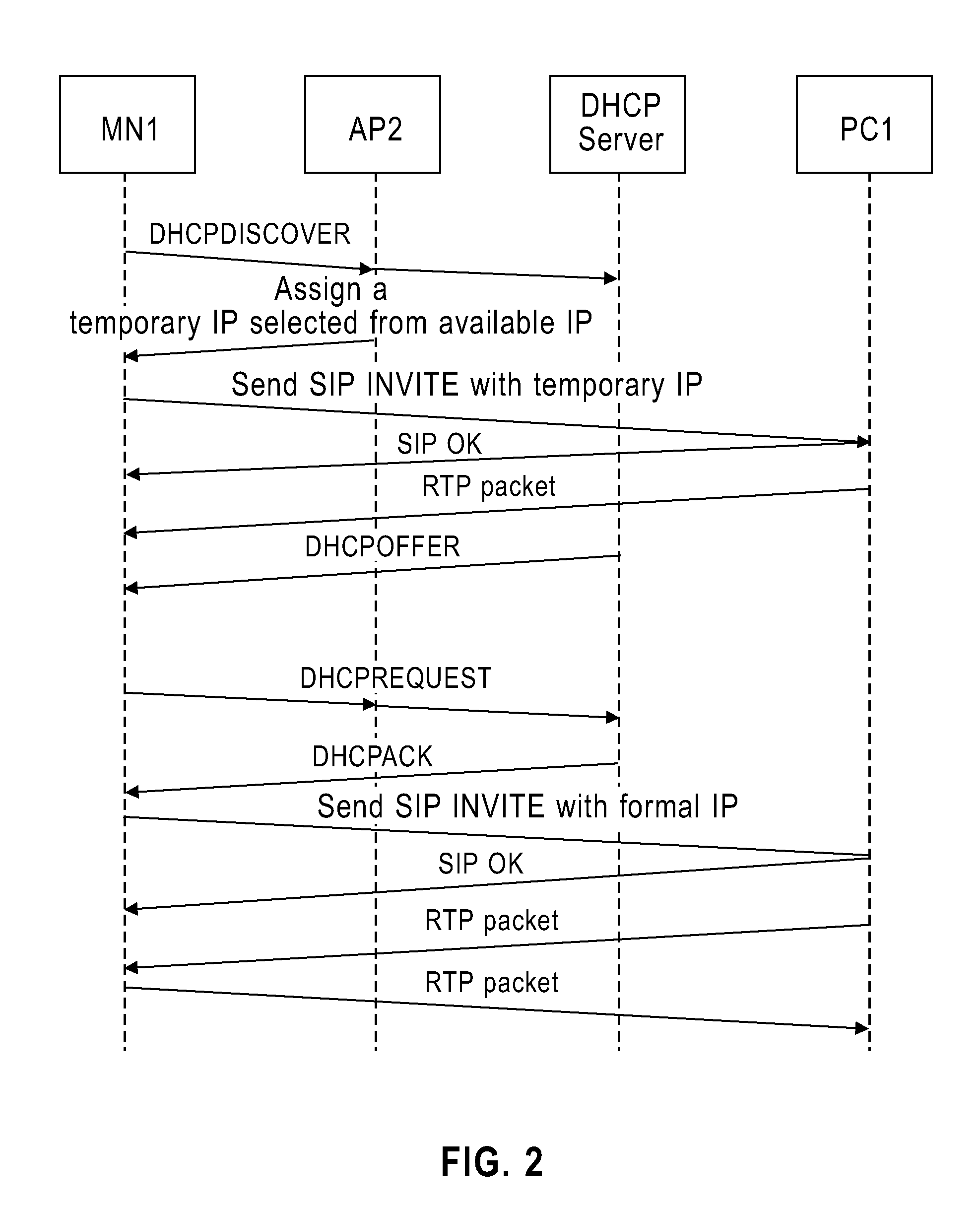
[0023]When mobile node MN1 enters another WLAN subnet SN2, the new subnet can detect its presence in the new subset by two methods. In the first the new subnet receives a broadcast message from AP2, and then d...


PUM


Abstract

A method and a wireless access point device for a network layer handoff of a wireless mobile node over a wireless local area network. The method includes detecting a wireless mobile node that has moved into the coverage area of the wireless access point device; maintaining an available IP address pool; selecting a temporary IP address from the IP access pool in response to the detection of the mobile node moving into the coverage area; and assigning a temporary IP address to the mobile node for use by the node during an interim period. The method produces a network layer handoff of a wireless mobile node over a local area network. Also provided is a computer readable article of manufacture tangibly embodying computer readable instructions for executing the steps of the method.

Description

CROSS-REFERENCE TO RELATED APPLICATION [0001]This application claims priority under 35 U.S.C. §119 from Chinese Patent Application No. 200810129456.2 filed on Jul. 31, 2008, the entire contents of which are incorporated herein by reference.BACKGROUND OF THE INVENTION[0002]1. Field of the Invention[0003]The present invention relates to a method for network layer handoff and more particularly to a method for network layer handoff over a wireless LAN.[0004]2. Description of Related Art[0005]Wireless local area network (WLAN), such as those which use the IEEE 802.11 protocol, have become increasingly popular and rapidly developing technology. When a user of WLAN moves from the coverage area of one access point (AP) to another, it is desirable that the network support rapid seamless handoff so that the user does not experience perceptible voice quality degradation. In many cases, especially in applications that use voice communication over a WLAN, an overlong period of time for network h...

Claims


Application Information

Patent Timeline
Patent Type & Authority Applications(United States)
IPC IPC(8): H04W36/00
CPCH04L61/2015H04W80/04H04W36/0011H04L61/5014
Inventor CHEN, LINLIANG, ZHIYONGLIN, YONGHUA
Owner IBM CORP
Why Eureka
Try Eureka