
Reinforced plate glass and method for manufacturing the same

a technology of reinforced plate glass and plate glass, which is applied in the field of plate glass, can solve the problems of difficult to realize a chemically reinforced, difficult to appropriately subject glass articles to physical physical, and difficult to produce reinforced plate glass, etc., and achieves high production efficiency and high outer appearance quality.

Inactive Publication Date: 2010-05-13
NIPPON ELECTRIC GLASS CO LTD
View PDF32 Cites 215 Cited by
  • Summary
  • Abstract
  • Description
  • Claims
  • Application Information

AI Technical Summary

Benefits of technology

The present invention aims to solve various problems associated with existing methods of manufacturing reinforced plate glass. The technical effects of the invention include providing a method that can reinforce the strength of a glass surface sufficiently and produce a reinforced plate glass of stable quality at high production efficiency, as well as a reinforced plate glass having a high size quality and stable surface strength. Additionally, the invention addresses the issue of conducting a partial reinforcement treatment of a plate glass by a spraying treatment or a paste treatment, instead of the entire reinforcement treatment, which requires much labor.

Problems solved by technology

However, only with the inventions which have been carried out so far, it is difficult to realize a chemically reinforced plate glass which has a high function and an excellent surface property, can realize a high production efficiency, is used for the applications such as various kinds of portable information terminals.
Therefore, there arises a problem in that a support method and the like must be devised variously as disclosed in Patent Document 2, or in that even a site that is not required to have high strength as a plate glass product is reinforced because the entire glass is treated in an ordinary reinforcement treatment.
However, various precise and minute cares must be taken in terms of the treatment facility, management technique, and the like, and hence, there arises a problem that the production of a reinforced plate glass requires much labor.
Therefore, it is difficult to appropriately subject the glass article to the physical processing such as cutting and cleaving which passes through or separates the glass article, after the chemical reinforcement.
If an attempt is made on the glass article so as to conduct such processing forcefully, due to the tensile stress inside the glass article, the glass article may be broken.
Alternatively, the glass article is not cut or cleaved at a desired position and only a finished article with a low precision is obtained, resulting in the problem with the production of a large number of defective products.
Further, there is a region where a large tensile force is applied on the cut surface of the glass article produced at a low efficiency percentage, and hence, an alkali metal component such as sodium in glass is likely to be deposited on the glass surface with time, which causes a problem in the weather resistance of the glass.
However, such steps increase labor for the production, and hence, there remains a problem in that a reinforced plate glass cannot be produced at high efficiency.

Method used


Image

  • Reinforced plate glass and method for manufacturing the same
  • Reinforced plate glass and method for manufacturing the same
  • Reinforced plate glass and method for manufacturing the same

Examples


example 1

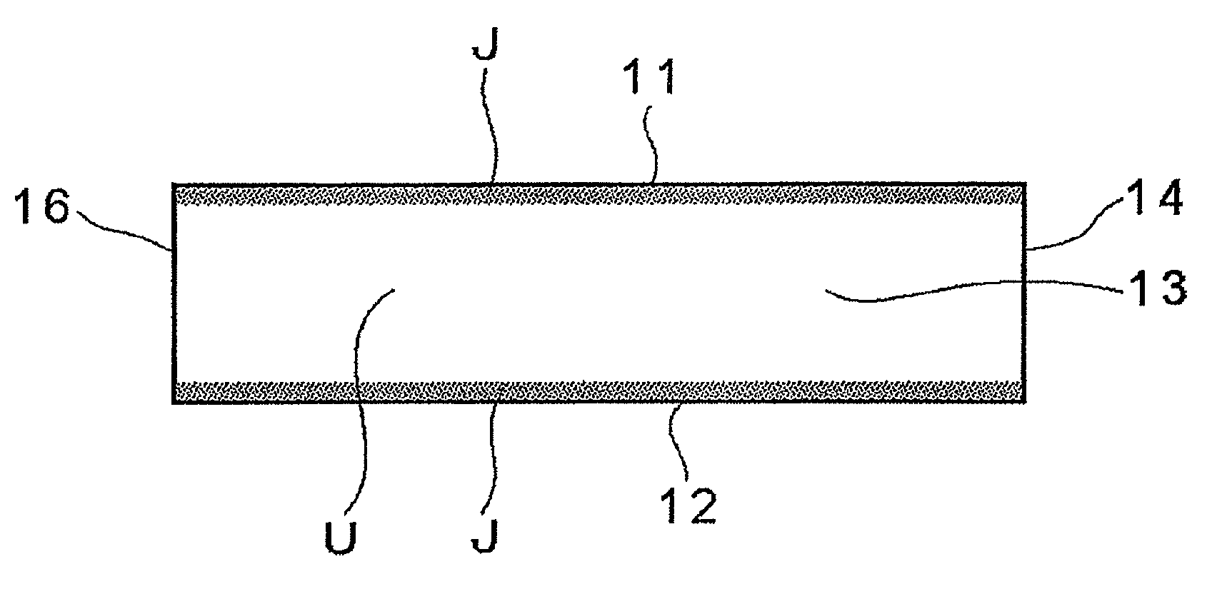
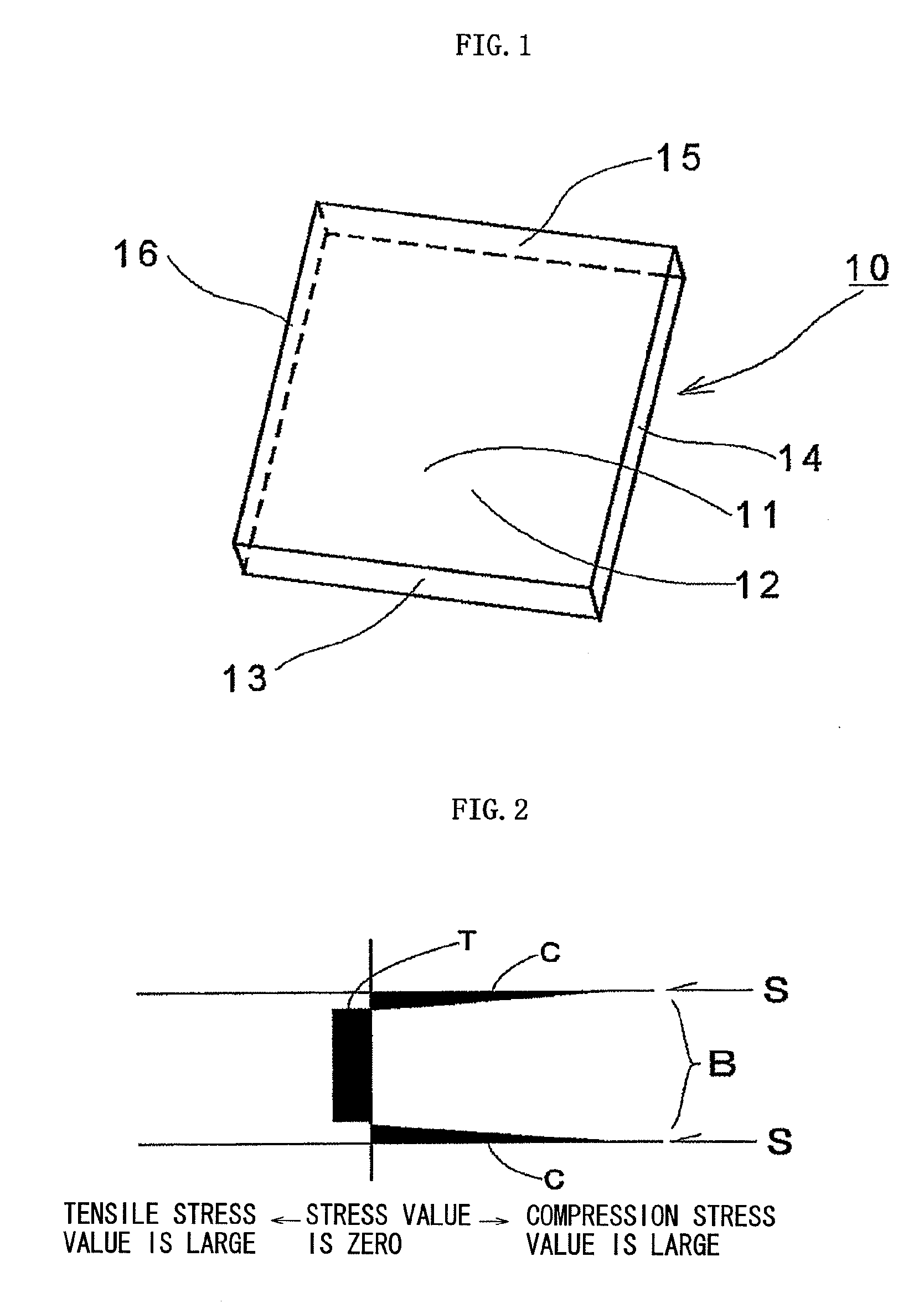
[0073]FIG. 1 is a perspective explanatory view of a reinforced plate glass of the present invention. The plate glass has a composition of 65.4% of SiO2, 22.0% of Al2O3, 4.2% of Li2O, 0.5% of Na2O, 4.7% of Li2O+Na2O, 0.3% of K2O, 1.5% of BaO, 2.0% of TiO2, 2.2% of ZrO2, 1.4% of P2O5, and 0.5% of As2O3 in percent % by mass of an oxide conversion.

[0074]A reinforced plate glass 10 is used for a transparent display panel to be mounted on a precision appliance, an electronic appliance, and the like such as a touch panel, a mobile telephone, and a mobile information terminal appliance. Therefore, it is necessary to reinforce only plate surfaces 11, 12 opposed to each other in a plate thickness direction, and further, a production efficiency needs to be enhanced. Therefore, the reinforced plate glass 10 is produced by soaking a parent plate glass having a large outer size of 500 mm (vertical size)×500 mm (horizontal size)×2 mm (plate thickness size) molded and ground by a roll-out method in...

example 2

[0083]Next, the performance and the like of the reinforced plate glass of the present invention is described.

[0084]Table 1 shows collectively the reinforcement conditions for obtaining a glass composition and a reinforced plate glass corresponding to the example of the present invention, the conditions for processing glass, strength measurement results of glass, and the like, and the detail thereof is described specifically.

TABLE 1ExampleSample No.12345678SiO265.465.465.461.668.365.460.560.5B2O3————10.9—1.81.8Al2O322.022.022.013.25.222.012.012.0Li2O4.24.24.21.9—4.2——Na2O0.50.50.58.011.30.513.813.8K2O0.30.30.35.3—0.34.04.0CaO————3.2—1.71.7ZnO———7.40.9—2.02.0BaO1.51.51.5——1.5——TiO22.02.02.02.1—2.0——ZrO22.22.22.2——2.24.04.0P2O51.41.41.4——1.4——AS2O30.50.50.5——0.5——Sb2O3———0.50.2—0.20.2Plate thickness X (mm)0.50.50.50.50.50.50.70.5Reinforce-Processing500475475400490500410410menttemperature (° C.)conditionsProcessing time24248243(Hr)Reinforce-Compression8707609309506108701,0501,100mentstr...

example 3

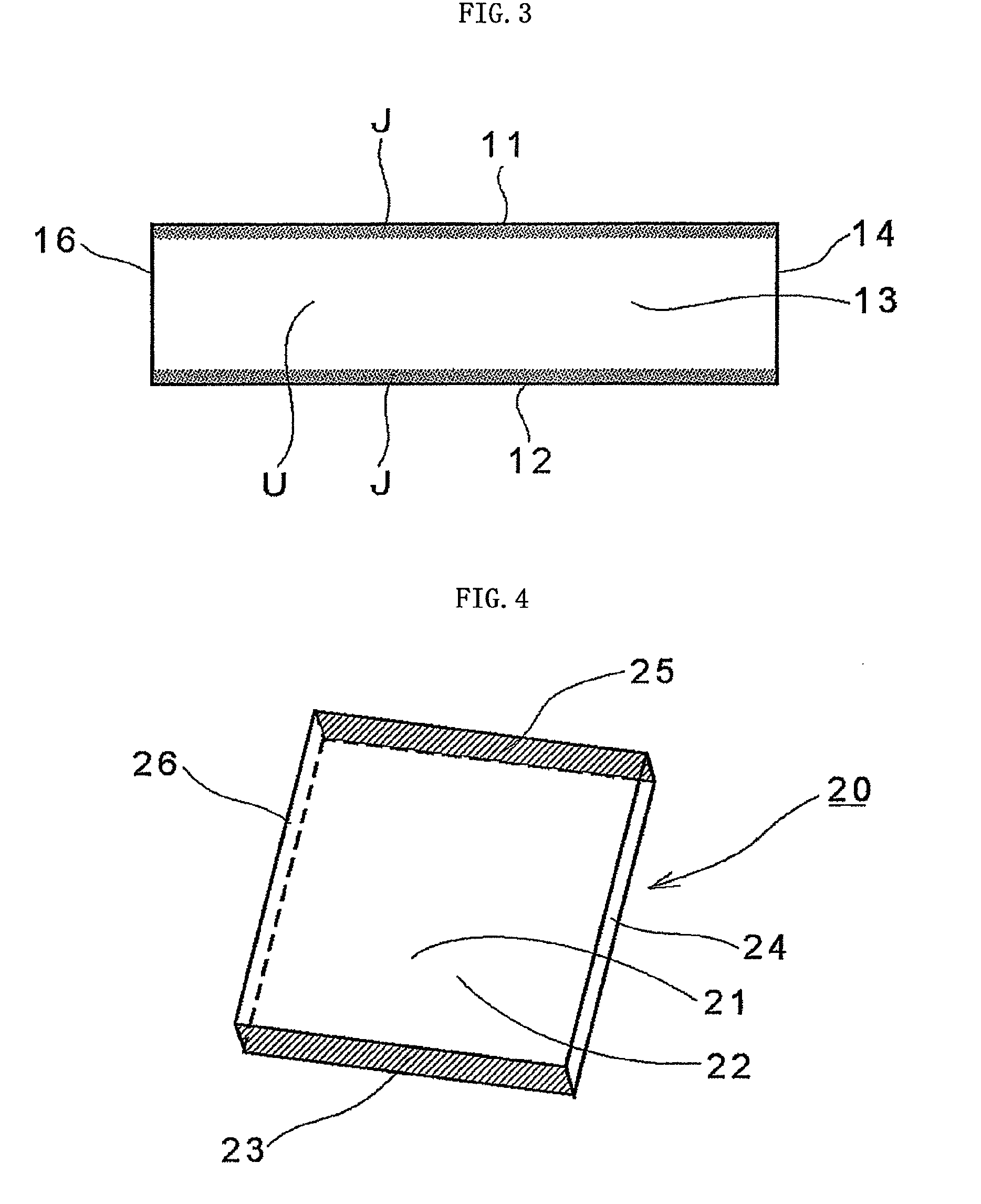
[0109]Further, FIG. 4 is a perspective explanatory view illustrating a reinforced plate glass as an example of the present invention in a different aspect from that of Example 1.

[0110]The reinforced plate glass 20 shown in FIG. 4 is different from the previous Example 1 in that ion exchange reinforcement is conducted during the processing of a reinforced plate glass. More specifically, a plate glass that is preliminarily formed into a strap shape is subjected to an ion exchange treatment, and only two plate end faces of the strap-shaped plate glass are cut by physical processing. Thus, in FIG. 4, among the plate end faces 23, 24, 25, and 26 of the reinforced plate glass, the plate end faces 23 and 25 are not subjected to ion exchange reinforcement, and the other plate end faces 24 and 26 are subjected to ion exchange reinforcement. In this respect, in the case of the previous Example 1, none of the plate end faces 13, 14, 15, and 16 are subjected to ion exchange reinforcement. It is...


PUM

PropertyMeasurementUnit
forceaaaaaaaaaa
scribing speedaaaaaaaaaa
transfer speedaaaaaaaaaa

Abstract

[Object] To provide a method of manufacturing a reinforced plate glass by which glass surface strength can be sufficiently increased, and a stable quality reinforced plate glass is manufactured at high production efficiency, and to provide a reinforced plate glass manufactured by the manufacturing method.[Solving Means] A reinforced plate glass (10) is formed of an inorganic oxide glass, and is provided with a compression stress layer by chemical reinforcement on plate surfaces (11, 12) opposed to each other in a plate thickness direction. Plate end faces (13, 14, 15, 16) have regions where a compression stress is formed and regions where no compression stress is formed.

Description

TECHNICAL FIELD[0001]The present invention relates to a plate glass used as a substrate material or a cover glass member to be mounted on an image display portion or an image input portion of various kinds of portable information terminals typified by a mobile phone and a PDA and an electronic appliance typified by a liquid crystal display, and a method of manufacturing the plate glass.BACKGROUND ART[0002]In recent years, as recognized in the progress of a digital technology involving all the industrial fields and the like, the information industry has been developed remarkably, and the prosperity thereof is presenting animated appearance in the same way as in the textile industry, steel industry, shipbuilding industry, or the like. Along with this, the technical innovation regarding various kinds of information-related terminals is expanding continuously, as in the increase in sales of mobile appliances such as a mobile phone, a digital camera, and a PDA and a large-type image disp...

Claims


Application Information

Patent Timeline
Patent Type & Authority Applications(United States)
IPC IPC(8): B32B17/06C03C15/00C03C21/00
CPCC03B33/023C03B33/027C03B33/033C03B33/04C03B33/074C03B33/091C03C21/002C03C3/091C03C3/093C03C19/00C03C23/0025C03C23/007C03C3/085Y02P40/57
Inventor SAWADA, MASAHIRO
Owner NIPPON ELECTRIC GLASS CO LTD
Learn More