Processes for Gasification of a Carbonaceous Feedstock

Inactive Publication Date: 2010-05-13
SURE CHAMPION INVESTMENT LTD
View PDF101 Cites 149 Cited by
  • Summary
  • Abstract
  • Description
  • Claims
  • Application Information

AI Technical Summary

Benefits of technology

[0028]The processes in accordance with the present invention can be useful, for example, for producing methane from various carbonaceous fe

Problems solved by technology

In doing so, the engineering complexity and overa

Method used


Image

  • Processes for Gasification of a Carbonaceous Feedstock
  • Processes for Gasification of a Carbonaceous Feedstock
  • Processes for Gasification of a Carbonaceous Feedstock

Examples


examples of specific embodiments

[0099]As described in more detail below, in one embodiment of the invention, the gasification catalyst can comprise an alkali metal gasification catalyst.

[0100]As described in more detail below, the carbonaceous feedstock can comprise any of a number of carbonaceous materials. For example, in one embodiment of the invention, the carbonaceous feedstock comprise one or more of anthracite, bituminous coal, sub-bituminous coal, lignite, petroleum coke, asphaltenes, liquid petroleum residues or biomass.

[0101]As described in more detail below, in certain embodiments of the invention, the carbonaceous feedstock is loaded with a gasification catalyst (i.e., to form a catalyzed carbonaceous feedstock) prior to its introduction into the catalytic gasifier. For example, the whole of the carbonaceous feedstock can be loaded with catalysts, or only part of the carbonaceous feedstock can be loaded with catalyst. Of course, in other embodiments of the invention, the carbonaceous feedstock is not l...

example 1

[0189]One embodiment of the processes of the invention is illustrated in FIG. 5. Therein, a carbonaceous feedstock (10) is provided to a feedstock processing unit (100) and is converted to a carbonaceous particulate (20) having an average particle size of less than about 2500 μm. The carbonaceous particulate (20) is provided to a catalyst loading unit (200) wherein the particulate is contacted with a solution comprising a gasification catalyst in a loading tank, the excess water removed by filtration, and the resulting wet cake dried with a drier to provide a catalyzed carbonaceous feedstock (30). The catalyzed carbonaceous feedstock is provided a catalytic gasifier (300).

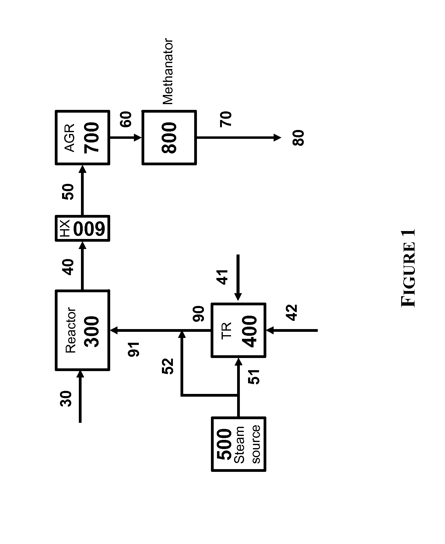
[0190]In the catalytic gasifier, the catalyzed carbonaceous feedstock (30) is contacted with a first gas stream (91) comprising carbon monoxide, hydrogen, and superheated steam under conditions suitable to convert the feedstock a second gas stream (40) comprising at least methane, carbon dioxide, carbon monoxide, h...

example 2

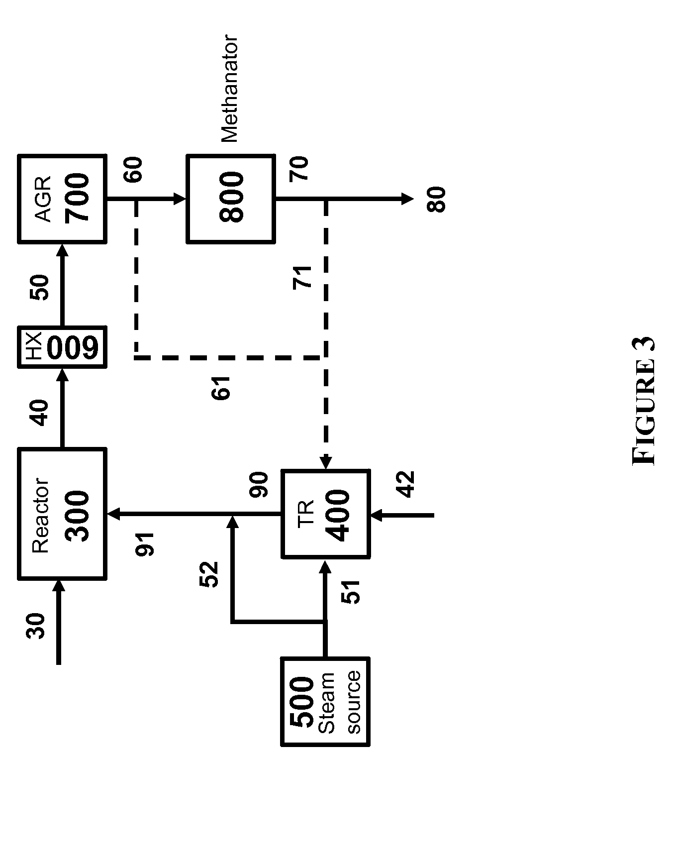
[0194]Another embodiment of the processes of the invention is illustrated in FIG. 6. Therein, a carbonaceous feedstock (10) is provided to a feedstock processing unit (100) and is converted to a carbonaceous particulate (20) having an average particle size of less than about 2500 μm. The carbonaceous particulate (20) is provided to a catalyst loading unit (200) wherein the particulate is contacted with a solution comprising a gasification catalyst in a loading tank, the excess water removed by filtration, and the resulting wet cake dried with a drier to provide a catalyzed carbonaceous feedstock (30). The catalyzed carbonaceous feedstock is provided a catalytic gasifier (300).

[0195]In the catalytic gasifier (300), the catalyzed carbonaceous feedstock (30) is contacted with a first gas stream (91) comprising carbon monoxide, hydrogen, and superheated steam under conditions suitable to convert the feedstock a second gas stream (40) comprising at least methane, carbon dioxide, carbon m...


PUM

PropertyMeasurementUnit
Fractionaaaaaaaaaa
Ratioaaaaaaaaaa
Molar ratioaaaaaaaaaa

Abstract

The present invention relates to processes for preparing gaseous products, and in particular, methane via the catalytic gasification of carbonaceous feedstocks in the presence of steam. The processes comprise using at least one methanation step to convert carbon monoxide and hydrogen in the gaseous products to methane and do not recycle carbon monoxide or hydrogen to the catalytic gasifier.

Description

CROSS REFERENCE TO RELATED APPLICATION[0001]This application claims priority under 35 U.S.C. §119 from U.S. Provisional Application Ser. No. 61 / 098,472 (filed Sep. 19, 2008), the disclosure of which is incorporated by reference herein for all purposes as if fully set forth.[0002]This application is related to commonly owned and concurrently filed U.S. patent application Ser. No. ______, attorney docket no. FN-0039 US NP1, entitled CHAR METHANATION CATALYST AND ITS USE IN GASIFICATION PROCESSES.FIELD OF THE INVENTION[0003]The present invention relates to processes for preparing gaseous products, and in particular, methane via the catalytic gasification of carbonaceous feedstocks in the presence of steam.BACKGROUND OF THE INVENTION[0004]In view of numerous factors such as higher energy prices and environmental concerns, the production of value-added gaseous products from lower-fuel-value carbonaceous feedstocks, such as petroleum coke and coal, is receiving renewed attention. The cata...

Claims


Application Information

Patent Timeline
IPC IPC(8): C07C1/04
CPCC01B3/34C10K1/165C01B2203/0233C01B2203/0244C01B2203/025C01B2203/0283C01B2203/0405C01B2203/0415C01B2203/0445C01B2203/045C01B2203/0455C01B2203/046C01B2203/047C01B2203/0475C01B2203/048C01B2203/0485C01B2203/06C01B2203/1058C01B2203/1064C01B2203/147C10J3/00C10J3/482C10J3/721C10J2300/093C10J2300/0956C10J2300/0959C10J2300/0973C10J2300/0986C10J2300/1662C10J2300/1671C10J2300/1675C10J2300/1687C10J2300/1807C10J2300/1884C10K3/04C10L3/08C10K1/004C10K1/005C10K1/122C10K1/143C10K1/16C01B3/48
Inventor ROBINSON, EARL T.SIRDESHPANDE, AVINASHGAL, ELIREILING, VINCENT G.NAHAS, NICHOLAS CHARLES
Owner SURE CHAMPION INVESTMENT LTD
Why Eureka
Try Eureka