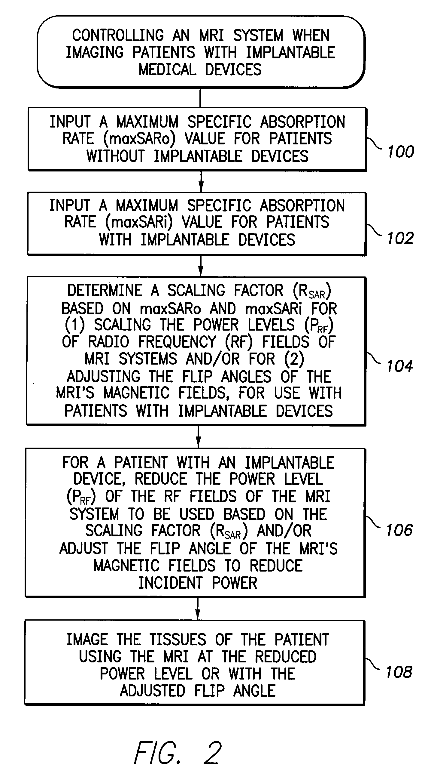
[0010]In accordance with a first general embodiment of the invention, systems and methods are provided for controlling MRI systems for safely imaging the tissues of patients with implantable medical devices, particularly AIMDs. Briefly, the systems and methods
exploit a scaling factor derived from predetermined SAR values for use in reducing the RF power of the MRI and / or for adjusting the
flip angle of the MRI to reduce incident power within the tissues of the patient. In use, the MRI
system initially determines appropriate RF power levels and flip angle sequences for a particular patient to be imaged without regard to the presence of the implantable
medical device in the patient. The MRI system then reduces RF power levels and adjusts flip angles using the scaling factor prior to imaging. With proper selection of the scaling factor, heating within the patient remains at safe levels during the MRI despite the presence of the implantable device. Also, with proper selection of the scaling factor, any MRI system validated for use on patients without implants likewise qualifies for validation on patients with implants, thus obviating the need to separately or individually validate MRI systems with different implantable devices, lead combinations, etc.
[0014]Hence, any MRI system validated for use by the FDA (or other appropriate government entity) on patients without implants should likewise qualify for validation on patients with implants, assuming PRF is scaled by RSAR or the flip angle is properly adjusted based on RSAR, thus obviating the need to separately or individually validate MRI systems with different implantable devices, lead combinations, etc. At least, any MRI system validated for use on patients without implants should be more easily validated for use on patients with implants, when exploiting these SAR-based techniques.
[0016]By exploiting the worst case
scenario, modeling and / or experimental validations are no longer required to ascertain maxSARi for all MRI systems or to determine different maxSARi values associated with each individual MRI system. However, in some implementations, it may be desirable to further specify different maxSARi values for use with different MRI machines, such that a unique RSAR value is determined for use with each MRI
machine. For example, one particular RSAR value is determined for use with MRI
machine A provided by Manufacturer A; whereas a different RSAR value is determined for use with MRI
machine B provided by Manufacturer B. Likewise, in some implementations, it may be desirable to further specify different maxSARi values for use with different implantable devices and leads, such that a unique RSAR value is determined for use with each model of implantable device or each model of device lead. For example, one particular RSAR value is determined for use with Pacemaker C provided by Manufacturer C; whereas a different RSAR value is determined for use with Pacemaker D provided by Manufacturer D. That is, rather than determining RSAR based on the single worst case
scenario, a plurality of RSAR values are obtained for use in different circumstances. The information can be exploited in the “
Implant Mode” of the MRI machines. These added levels of specificity permit generally higher RF power levels to be used in most cases so as to provide better MRI images, while still ensuring patient safety.
[0019]When using the device-activated
Implant Mode of the MRI system, rather than using a maxSARi value validated for general patient populations, a maxSARi value can instead be employed that takes into account specific attributes of the particular
medical device implanted in the patient to be imaged. The use of these “device-specific” maxSARi values may be helpful in allowing the MRI system to use more RF power than would be permitted based on a general “worst case” maxSARi, thus yielding higher resolution images in at least some patients. For example, implantable devices are increasingly equipped with
RF filters or other devices for mitigating the effects of MRI fields. Patients with such devices can be safely imaged with stronger RF fields than would be used if using a general “worst case” maxSARi to scale the RF power. Accordingly, information pertaining to particular makes / models of devices that might be implanted within patients is programmed into the MRI system in advance. The MRI system then uses the stored information in conjunction with the information transmitted from the device to determine the appropriate scaling factor to be used for that patient.
[0021]In accordance with a second general embodiment of the invention, rather than reducing the power of the RF fields of the MRI system for patients with implants, RF power attenuation materials, such as blankets, jackets or pads containing suitable
dielectric or resistive /
conductive materials, are instead placed around the patient, particularly around the portions of the patient in which devices are implanted. For example, blankets or pads containing
dielectric or resistive /
conductive materials may be wrapped around the chest of a patient with a pacemaker or ICD. The RF power attenuation materials reduce the RF power radiating patient tissues in the vicinity of the implantable device by an amount sufficient to ensure that maxSARo is not exceeded within those tissues. In some implementations, different articles / materials with different thicknesses are tested and validated in advance to achieve different reductions in RF power within patient tissues. MRI personnel then select the particular RF power attenuation articles / materials that are appropriate for a given patient similar to the information input into MRI before scans such as patient weight etc. Patient-specific attributes, such as whether the medical devices implanted therein are equipped with
RF filters, may also be taken into account when selecting the articles / materials to be used. For example, blankets of differing thickness may be provided. MRI personnel then select the appropriate thickness for use with a given patient based, in part, on the attributes of the implanted
medical device or other patient attributes.

