
Travel energy learning device, method, and program

a learning device and travel energy technology, applied in the direction of electric devices, process and machine control, navigation instruments, etc., can solve the problems of difficult to accurately derive complicated calculation, and difficulty in obtaining precise and accurate parameters used in calculation, so as to achieve accurate derivation of the energy required for traveling a road section

Inactive Publication Date: 2010-05-13
AISIN AW CO LTD
View PDF5 Cites 31 Cited by
  • Summary
  • Abstract
  • Description
  • Claims
  • Application Information

AI Technical Summary

Benefits of technology

[0005]The present invention was devised in light of the foregoing problem, and the present invention provides art for accurately deriving the energy required for traveling a road section.
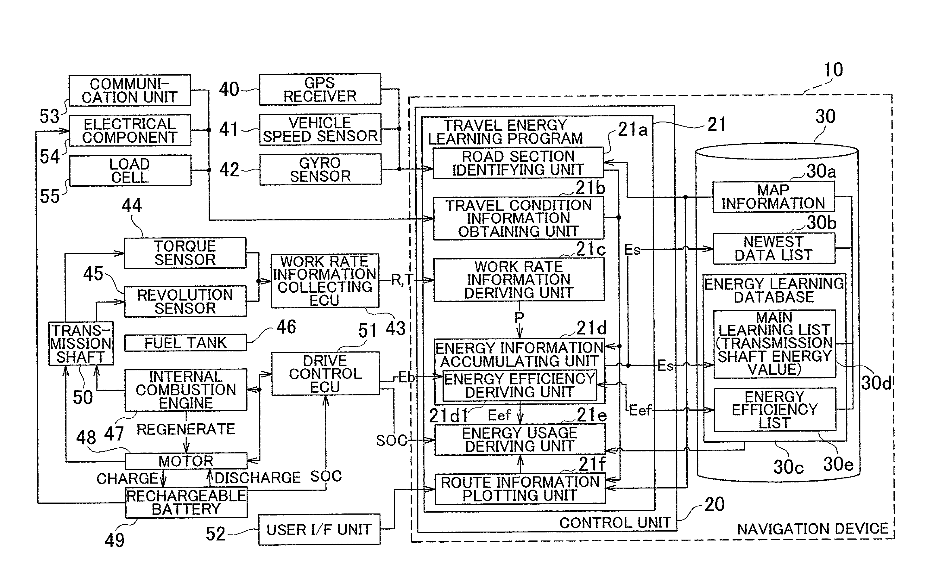
[0006]To achieve the above, the present invention identifies a road section where the host vehicle is currently located and obtains travel condition information that indicates a travel condition when the host vehicle traveled the road section. The present invention also derives information that indicates a work rate of a transmission shaft based on a revolution of the transmission shaft that transmits a driving force from a drive source of the host vehicle to a wheel and torque transmitted by the transmission shaft, and identifies information that indicates the energy required for traveling the road section based on the information that indicates the work rate. The information indicating the required energy is linked to the road section and the travel condition information, and the linked information is accumulated. In other words, the revolution and torque of the transmission shaft are directly obtained from the transmission shaft, and the actual output work rate of the transmission shaft is derived from the revolutions and transmitted torque. In addition, the work rate of the transmission shaft is then used to derive the output energy required by the host vehicle to travel through a particular road section, and the output energy is linked to the travel condition information. Therefore, the output energy required for traveling the road section can be determined per travel condition, and the output value (the energy required to travel through the road section) may be derived more accurately using a simple calculation compared to a configuration that calculates the required output energy value using a travel speed pattern, road grade, road friction coefficient, vehicle weight, air resistance, or the like, regardless of the travel condition.
[0009]In other words, if the host vehicle's weight differs when traveling the road section, the energy required for driving the host vehicle also differs. Therefore, linking the host vehicle's weight and information indicating the energy required for traveling the road section enables a more accurate determination of the energy required for traveling the road section. Additionally, if the usage state of the electrical component in the host vehicle differs when traveling the road section, the electric power supplied from the rechargeable battery to the electrical component also differs. Therefore, linking the usage state of the electrical component and information indicating the energy required for traveling the road section enables a more accurate determination of the energy required for traveling the road section. Furthermore, if the weather condition differs when the host vehicle travels the road section, the energy required for driving the host vehicle also fluctuates due to differences in the friction coefficient of the road surface and the like. Therefore, linking the weather condition and information indicating the energy required for traveling the road section enables a more accurate determination of the energy required for traveling the road section.
[0011]For example, the host vehicle's weight may be classified into a plurality of categories depending on size, and the weight of the host vehicle when traveling the road section obtained. The category to which the obtained weight belongs may then be determined, and the identified category set as the traveling condition information. The electric power consumption of the electrical component may also be classified into a plurality of categories depending on magnitude, and the category to which the electric power consumption for the usage state of the electrical component when the host vehicle traveled the road section belongs then determined. Furthermore, the weather condition may also be classified into a plurality of categories, and the category to which the weather condition when the host vehicle traveled the road section belongs then determined. As explained above, by determining the appropriate category and using information that indicates the category as the travel condition information, the weight of the host vehicle, which is continuously variable, can be easily determined, and the travel condition information defined in a simple manner.
[0018]If the travel condition is classified using categories defined in advance, the categories may be constituted so as to dynamically change. For example, the division of categories is considered excessive if the difference in the energy required for traveling the road section for travel conditions belonging to different categories is equal to or less than a predetermined standard. When excessive division of categories is judged, combining two categories enables adjustment of the number of categories so that a significant number of categories can be achieved over the course of learning even if the travel conditions are classified based on an excessive division of categories at the start of learning. Obviously, the number of categories may also be increased over the course of learning. For example, if two or more peaks appear in a distribution (histogram) of the energy required for traveling the road section in a certain category, the category may be divided into two or more categories to more precisely classify the travel condition. It should be noted that when increasing the number of categories based on the energy distribution, suitable categories may be easily defined with the use of an analysis method such as discriminant analysis.

Problems solved by technology

However, it is difficult to obtain precise and accurate parameters that are used in the calculation, and the calculation is complicated due to the many parameters involved.
It is thus difficult for the related art to accurately derive the energy required for traveling a road section.

Method used


Image

  • Travel energy learning device, method, and program
  • Travel energy learning device, method, and program
  • Travel energy learning device, method, and program

Examples


Embodiment Construction

[0028]Hereinafter, an embodiment of the present invention will be described in the following order.

(1) Configuration of Travel Energy Learning Device

(2) Travel Energy Learning Processing

[0029](2-1) Energy Learning Processing

[0030](2-2) Energy Efficiency Deriving Processing

[0031](2-3) Learning Data Usage Processing

(3) Other Embodiments

(1) Configuration of Travel Energy Learning Device

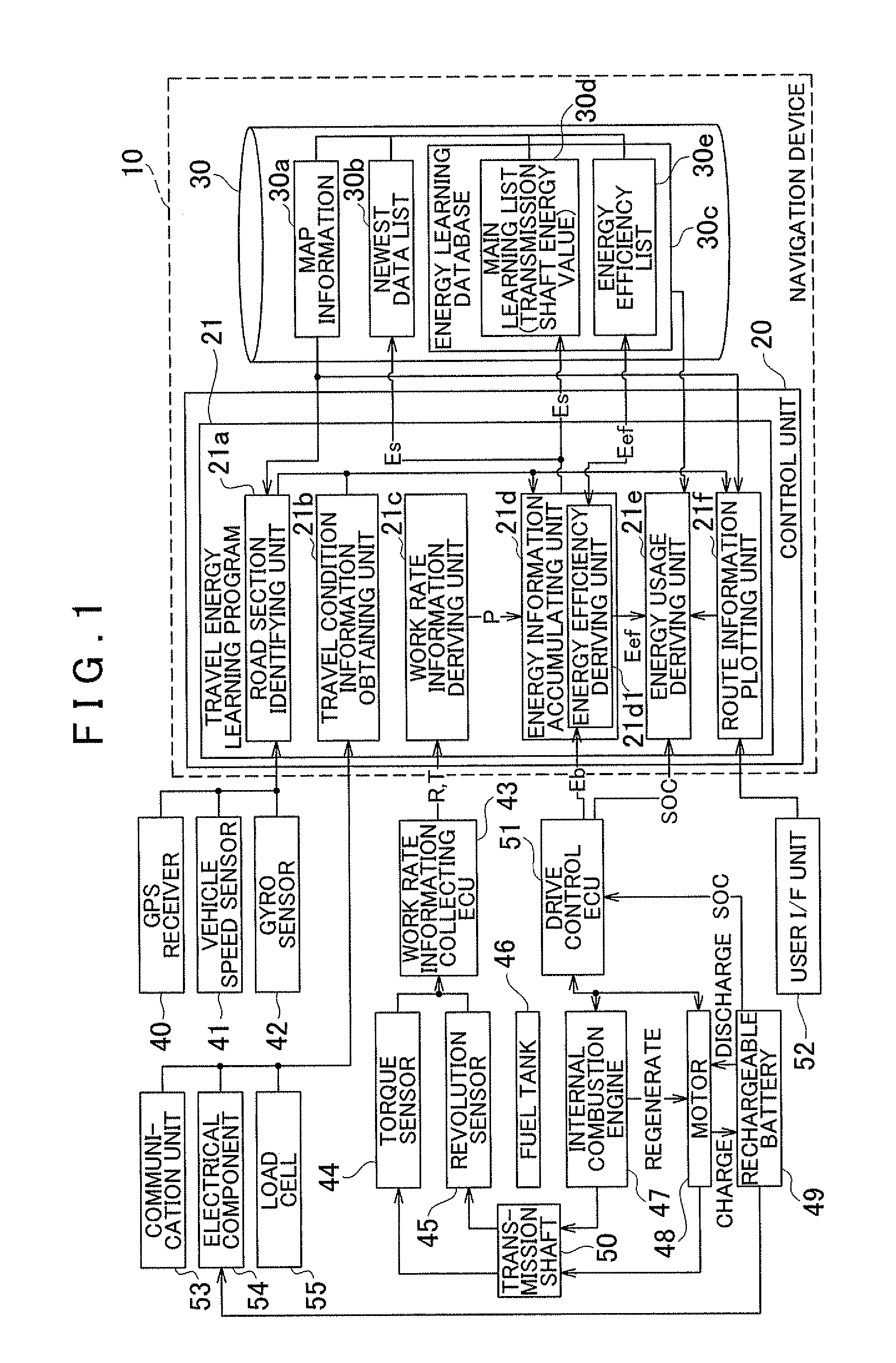
[0032]FIG. 1 is a block diagram showing the configuration of a travel energy learning device installed in a vehicle. The travel energy learning device of the present embodiment is implemented by a navigation device 10. The navigation device 10 includes a control unit 20 that has a CPU, a RAM, a ROM, and the like, and a memory medium 30. The navigation device 10 executes programs accumulated in the memory medium 30 and the ROM using the control unit 20. In the present embodiment, a travel energy learning program 21 is one such program that may be executed by the control unit 20. To implement the learning ...


PUM


Abstract

A travel energy learning device includes: a road section identifying unit that identifies a road section where a host vehicle is currently located; a travel condition information obtaining unit that obtains travel condition information that indicates a travel condition when the host vehicle traveled the road section; a work rate deriving unit that derives information indicating work rate of a transmission shaft based on rate of rotation of the transmission shaft and torque transmitted by the transmission shaft; and an energy information accumulating unit that derives required energy information indicating the energy required for traveling the road section based on the derived information that indicates the work rate during travel of the road section, links the derived required energy information to the road section and the travel condition information, and accumulates the required energy information.

Description

INCORPORATION BY REFERENCE[0001]The disclosure of Japanese Patent Application No. 2008-287211 filed on Nov. 7, 2008 including the specification, drawings and abstract is incorporated herein by reference in its entirety.BACKGROUND OF THE INVENTION[0002]The present invention relates to a travel energy learning device, method, and program for a vehicle provided with a rechargeable battery.DESCRIPTION OF THE RELATED ART[0003]Conventionally, a usage schedule for an engine and a motor in a hybrid vehicle is set such that the amount of fuel consumed during travel on a route to a destination is minimized. Japanese Patent Application Publication No. JP-A-2000-333305 describes that, based on a driving history of a driver, road information specifying a route, vehicle information, and the like, an output energy value required to travel the route is calculated.SUMMARY OF THE INVENTION[0004]According to JP-A-2000-333305, the required output energy value is calculated based on the travel speed pat...

Claims


Application Information

Patent Timeline
IPC IPC(8): B60W20/00B60L50/16
CPCB60K6/48Y02T10/6286B60W10/06B60W10/08B60W20/00B60W2510/104B60W2510/105B60W2510/244B60W2520/10B60W2520/14B60W2530/10B60W2550/12B60W2550/20B60W2550/402Y02T10/56Y02T10/6221B60L2240/486B60W40/10B60W2050/0031B60W2050/0088B60L58/12B60W2554/00B60W2555/20B60W2556/50Y02T10/62Y02T10/70B60L3/00B60W10/26B60W2520/06B60W20/11Y02T10/40
Inventor KATO, KAZUYAHIDAKA, TATSUYA
Owner AISIN AW CO LTD
Learn More