[0010]The present invention solves the problems mentioned and discloses a device for the control of aircraft and water craft, which device provides a high degree of robustness to unintended pilot intervention, and allows very considerable scope of forces for the action of the autopilot. Furthermore, any manual intervention in the control system by the pilot at acceptable breakout forces continues to be ensured. Finally, the invention makes it possible to maintain a pre-set trim point even after manual control has been carried out.
[0016]The device further comprises a trim coupling which when operated makes it possible to reduce the forces acting on the manual control unit, which forces are to be applied in order to displace the manual control unit from the
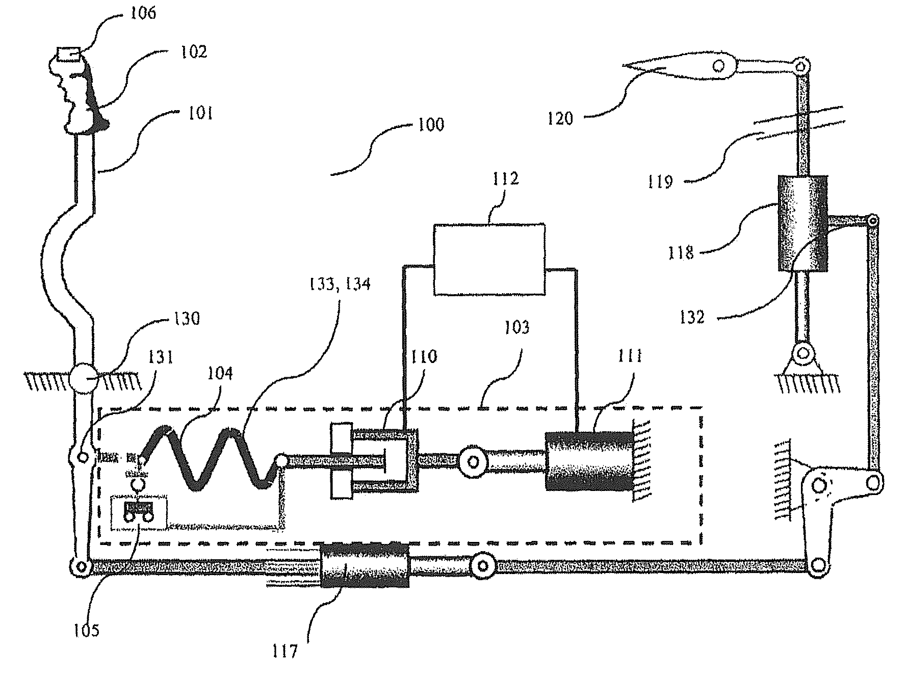
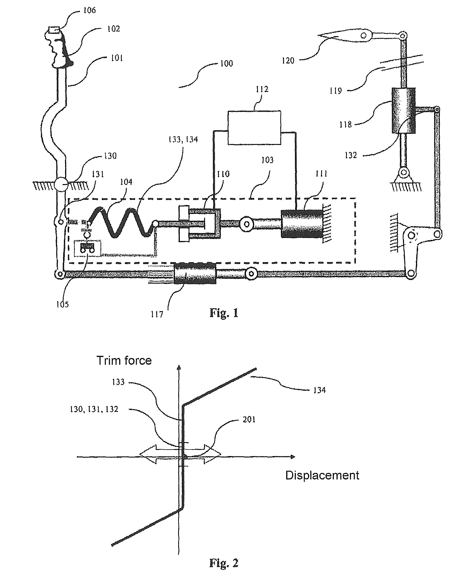
neutral position. A control device could, for example, be designed such that by means of a return spring artificial breakout forces acting on the manual control unit are generated. One end of this return spring is then connected to the manual control unit, while the other end is affixed. Reduction of the forces acting on the manual control unit can then, for example, be achieved in that the trim coupling is located between the return spring and the fastening so that when the trim coupling is operated the return spring is functionally decoupled from the manual control unit and in this way the forces are reduced by the forces caused by the return spring.
[0017]Finally, the device comprises a trim control unit which stores the trim point which existed prior to operation of the trim coupling, and, for example in a first mode, makes it possible to retain or restore this trim point even after renewed coupling of the trim coupling. Such a device makes it possible for a pilot both to carry out manual control with reduced control forces, and to cause the trim point to be retained.
[0021]In a further embodiment the device further comprises a final control element which, either directly or indirectly by way of the manual control unit, acts on the means for controlling the direction of movement. A final control element can, for example, be a trim motor or a final control motor whose one end is connected to the trim coupling and whose other end is affixed. It is then possible to set the trim point by way of the trim motor. This arrangement can involve a
stepper motor which is selected by way of a trackpoint, a trackball or generally a direction-dependent switch so that the trim point can be set as accurately as possible.
[0024]Furthermore, the device can comprise an autopilot. The latter can, for example, by means of the trim motor act on the means for controlling the direction of movement. Furthermore, between the manual control unit and the means for controlling the direction of movement the device can comprise a so-called SAS (Stability Augmented
System) / SEMA (Smart
Electromechanical Actuator)
actuator which carries out short-term stabilisation functions and is also controlled by the autopilot. This SAS / SEMA
actuator then supplements control by way of the trim motor, which control is responsible for overarching control of the direction and movement, thus making it possible to carry out stabilising measures, for example compensating reactions to wind gusts or
waves.
[0025]The influence the autopilot has on the direction of movement of the vehicle can be reduced by operating the trim coupling or by operating the manual control unit. For example, by way of operating the trim coupling, the autopilot can be decoupled completely from controlling the direction of movement, i.e. it can be completely degraded. However, it is also possible for the autopilot to be only partly degraded and to continue to be able to act to a reduced extent on the direction of movement of the vehicle. In particular, the autopilot can continue to act on stabilising the vehicle, and in this way it can, for example, react in a compensating manner to any wind gusts or
waves. This can be made possible by means of the SAS / SEMA
actuator, because, unlike the trim motor, the SAS / SEMA actuator is not decoupled by decoupling the trim coupling from the control system. The autopilot is thus only partly degraded by operation of the trim coupling and can continue to carry out stabilising measures by way of the SAS / SEMA actuator.

