Apparatus and method for cooling an exhaust gas

Inactive Publication Date: 2010-05-27
GM GLOBAL TECH OPERATIONS LLC
View PDF32 Cites 17 Cited by
  • Summary
  • Abstract
  • Description
  • Claims
  • Application Information

AI Technical Summary

Benefits of technology

[0008]In another exemplary embodiment of the present invention, a method for cooling an exhaust gas of an exhaust treatment device of an engine is provided, the method comprising: directing the exhaust gas through a first fluid conduit having a variable nozzle opening defined by a shape memory alloy extending from the first fluid conduit, the variable nozzle opening being received in an inlet end of a second fluid conduit, the variable nozzle opening being disposed in the second fluid conduit proximate to the inlet end of the second fluid conduit such that a fluid inlet opening is disposed about an outer periphery of the shape m

Problems solved by technology

Often, the required exhaust gas conditions cannot always be achieved during normal operation of the engine.
Resistance to exhaus

Method used


Image

  • Apparatus and method for cooling an exhaust gas
  • Apparatus and method for cooling an exhaust gas
  • Apparatus and method for cooling an exhaust gas

Examples


Example

[0021]In accordance with an exemplary embodiment of the present invention an exhaust gas cooling apparatus is provided. In one exemplary embodiment, the exhaust gas cooling apparatus utilizes a variable orifice venturi to introduce cooling gases into an exhaust gas of an engine. In one exemplary embodiment, the variable orifice venturi is used to cool an exhaust gas of an after-treatment device of the engine.

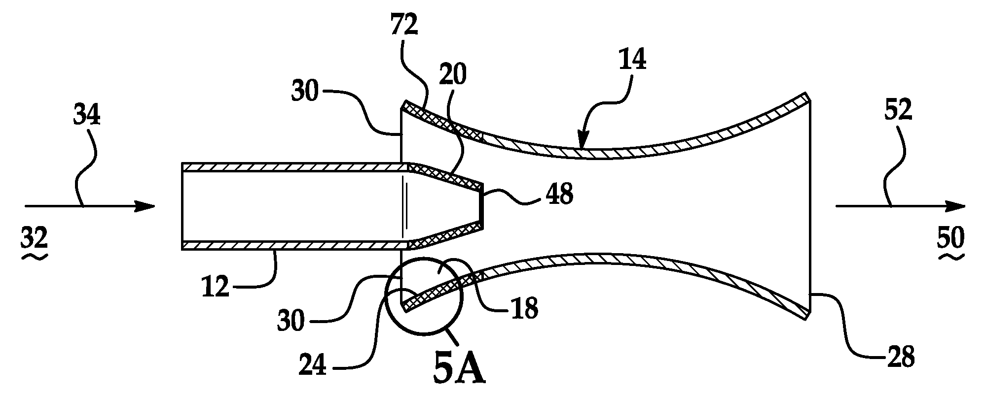
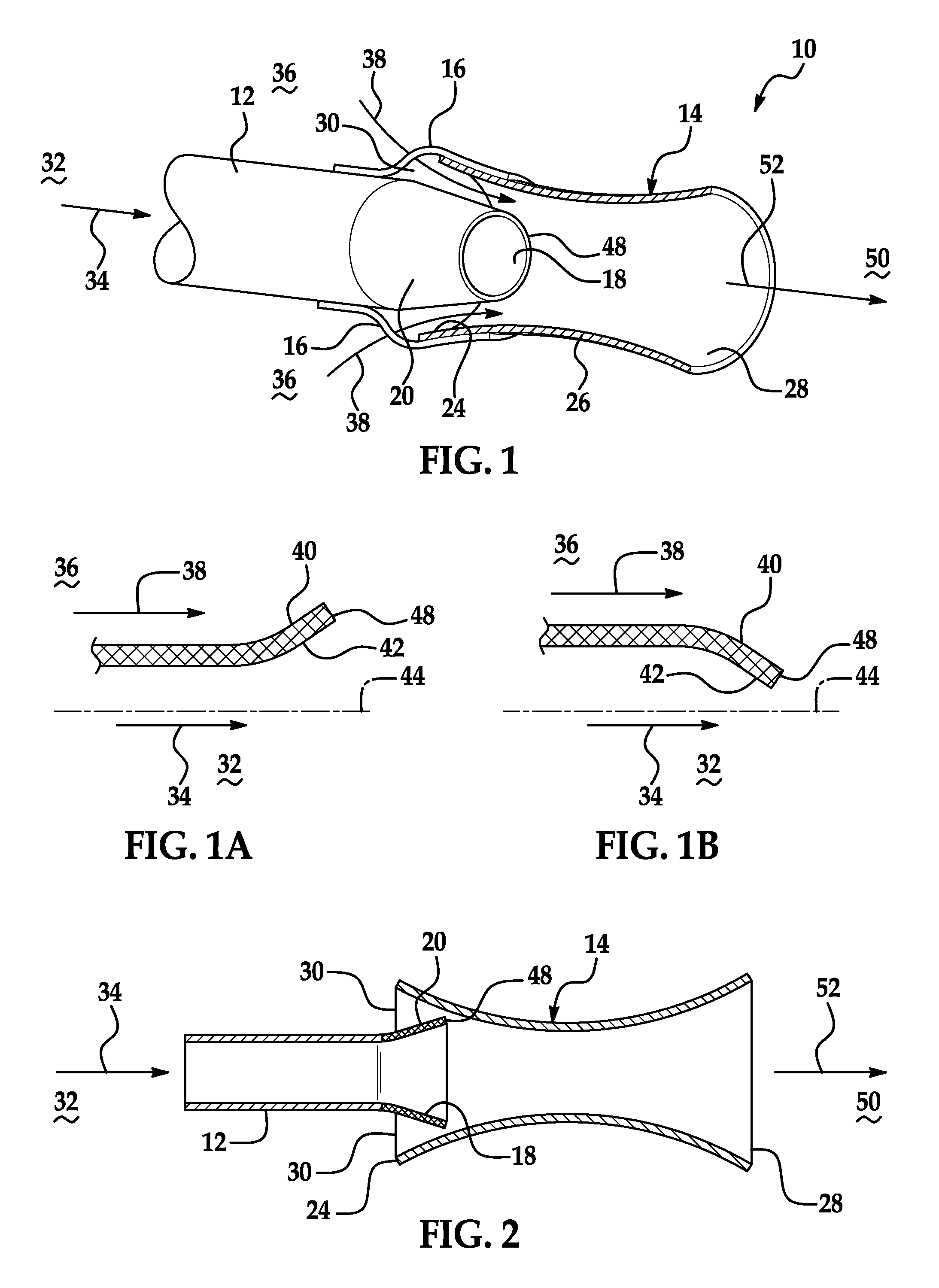
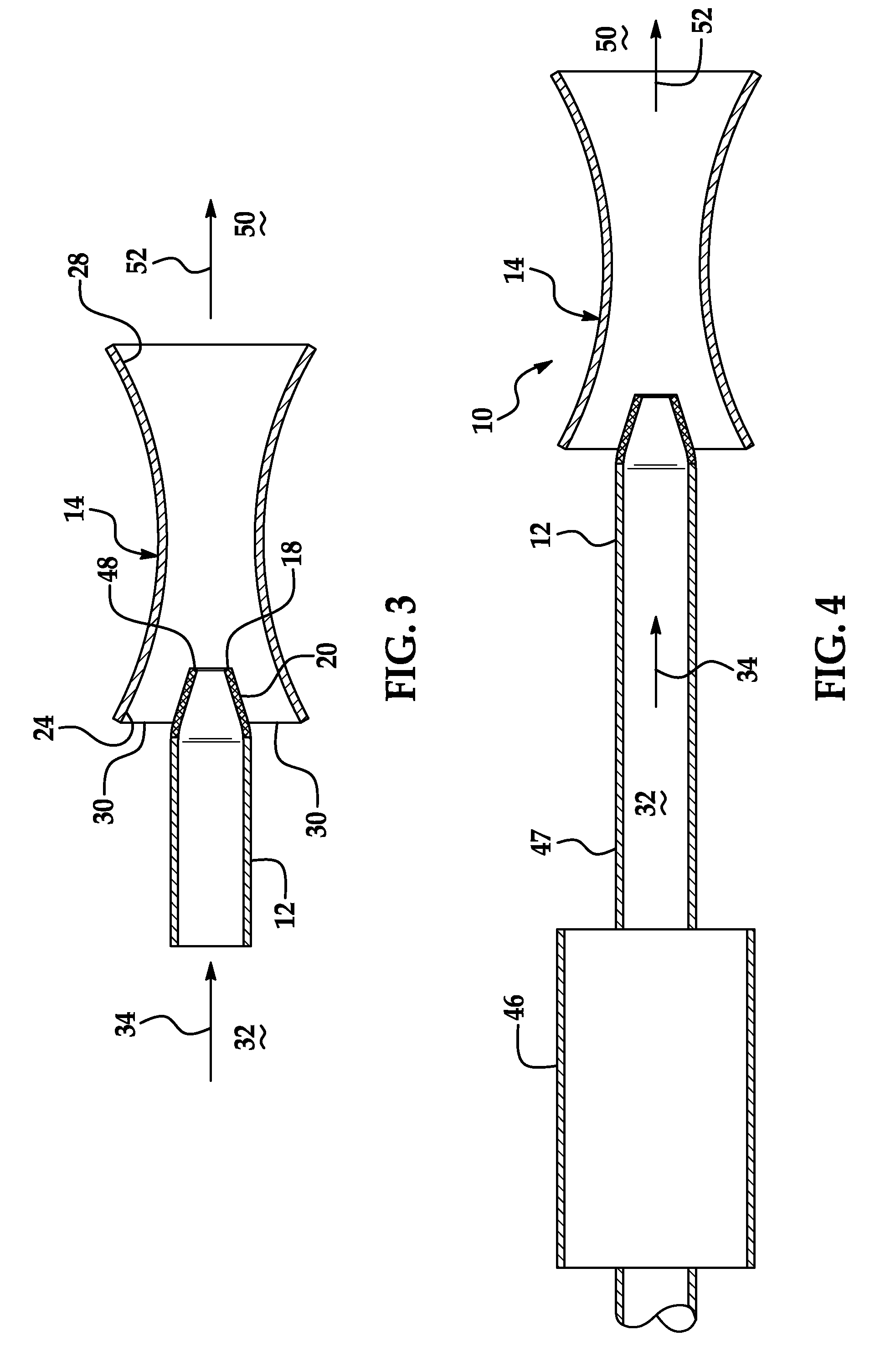
[0022]In accordance with an exemplary embodiment of the present invention, the variable orifice venturi is disposed downstream from an exhaust of an after-treatment device and upstream from an exit of the exhaust system (e.g., exhaust into ambient air). The variable orifice venturi uses a nozzle upstream of the exit of the exhaust pipe or system, which empties into a larger pipe, in order to produce a venturi.

[0023]The variable orifice venturi expands and contracts to introduce cooling gases into the exhaust stream as well as increase a velocity of the exhaust gas exiting the no...


PUM


Abstract

An exhaust gas cooling apparatus and method for cooling an exhaust gas is provided. The exhaust cooling apparatus having a first fluid conduit having a variable nozzle opening disposed at one end of the first fluid conduit, the variable nozzle opening being defined by a shape memory alloy extending from the first fluid conduit; and a second fluid conduit having an inlet end and an outlet end, the variable nozzle opening being disposed in the second fluid conduit proximate to the inlet end of the second fluid conduit such that a fluid inlet opening is disposed about an outer periphery of the variable nozzle opening and an inner surface of the inlet end of the second fluid conduit, the shape memory alloy varying the size of the variable nozzle opening by moving toward or away from a center line of the first fluid conduit in response to a temperature of an exhaust gas flowing through the first fluid conduit.

Description

FIELD OF THE INVENTION[0001]Exemplary embodiments of the present invention are related to a fluid entrainment apparatus and, more specifically, to a fluid entrainment apparatus to cool an exhaust gas.BACKGROUND[0002]Manufacturers of vehicles that employ internal combustion engines, more particularly diesel engines, are under increased pressure to comply with current and future emission standards for the release of oxides of nitrogen (NOx), particularly nitrogen monoxide (NO), as well as unburned and partially oxidized hydrocarbons (HC), carbon monoxide (CO), particulate matter, and other emissions, such as hydrogen sulfide (H2S) and ammonia (NH3). In order to reduce the previously mentioned emissions of a diesel engine, the diesel engine is typically operated with exhaust gas after-treatment system or systems through which the exhaust gas of the diesel engine flows and is treated.[0003]Exhaust gas after-treatment systems typically include one or more after-treatment devices, such as...

Claims


Application Information

Patent Timeline
IPC IPC(8): F01N3/02F01N3/00
CPCF01N3/05F01N13/082Y02T10/20F01N2470/30F01N2270/02Y02T10/12
Inventor GARCIA, LINDAFREESE, V, CHARLES E.VOSZ, ADAM
Owner GM GLOBAL TECH OPERATIONS LLC
Why Eureka
Try Eureka