Heating cooker

a technology for cookers and heating chambers, which is applied in the field of heating cookers, can solve the problems of increased pressure in the tank and the heating chamber, increased risk of overheating damage, and inconvenience in water supply

Active Publication Date: 2010-05-27
SHARP KK
View PDF10 Cites 11 Cited by
  • Summary
  • Abstract
  • Description
  • Claims
  • Application Information

AI Technical Summary

Benefits of technology

[0007]Accordingly, an object of the present invention is to provide a heating cooker in which a water level within a pot that serves for generating steam can be detected correctly at all times.
[0017]With the above construction, when the water in the pot has kept boiling for a predetermined time, the pump is controlled by the water supply control section so that an amount of water necessary to suppress the boiling is supplied to the pot. Accordingly, in the case where the steam pressure in the closed space ranging from the pot to the heating chamber increases, causing the water in the auxiliary tank to be forced up, so that the water level in the pot and the water level in the auxiliary tank are different from each other, the water boiling in the pot is temporarily suppressed and the steam pressure in the closed space is lowered, with the result that the water level in the auxiliary tank returns to a normal one. Thus, it becomes possible to correctly detect the water level in the pot by detecting the water level in the auxiliary tank.
[0021]As is apparent from the above description, in the heating cooker of this invention, when the water in the pot has kept boiling for a predetermined time, the pump is controlled by the water supply control section so that an amount of water necessary to suppress the boiling is supplied to the pot. Therefore, in the case where the steam pressure in the closed space ranging from the pot to the heating chamber increases so that the water in the auxiliary tank communicating with the bottom portion of the pot is forced up, causing the result that the water level in the pot and the water level in the auxiliary tank to be different from each other, the water boiling in the pot is temporarily suppressed and the steam pressure in the closed space is lowered, with the result that the water level in the auxiliary tank returns to a normal one. Thus, by detecting the water level in the auxiliary tank by means of the water level sensor from this on, the water level in the pot can correctly be detected.

Problems solved by technology

Due to this, even if the tank is emptied, the heating chamber is continued to be heated, accompanied by a risk of overheating damage, catching fire or the like.
Further, since the tank is fixed, there is an inconvenience that the water supply has to be done by using a water container for water-carrying use.
In the case where the water level in the tank for generating steam is detected by the water level sensor of the auxiliary tank, unfortunately, there is a problem as shown below.
That is, since the fixed tank is closed, continued heating of the heating chamber causes the generated steam to become increasingly filled in the tank and the heating chamber, which in turn causes pressures in the tank and the heating chamber to increase due to the difference in volume between water and steam, the latter being larger.
In this case, because the water level sensor outputs a normal value, the fixed tank is not supplied with water, accompanied by a risk of heating without water.

Method used


Image

  • Heating cooker
  • Heating cooker
  • Heating cooker

Examples


Embodiment Construction

[0029]The heating cooker of the invention will be described using examples shown in the drawings.

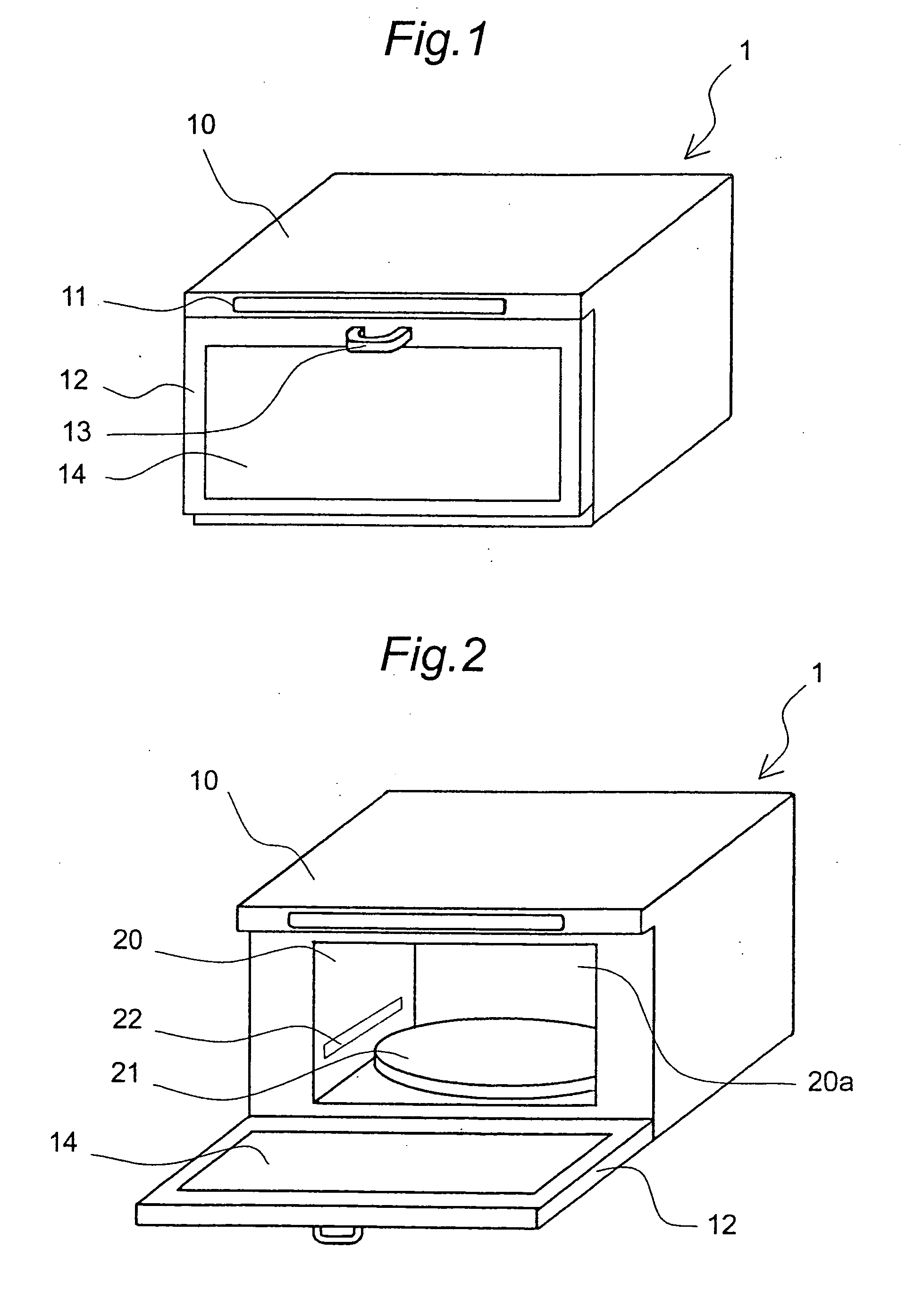
[0030]FIG. 1 is an external perspective view of a heating cooker 1 according to the present embodiment of the invention. The heating cooker 1 is schematically constructed as follows. A front upper portion of a rectangular parallelepiped cabinet 10 is provided with an operation panel 11, and a door 12, which is rotatable around a lower end side of the cabinet, is provided under the operation panel 11. An upper portion of the door 12 is provided with a handle 13, and the door 12 is provided with a window 14 made of thermal glass.

[0031]FIG. 2 is an external perspective view of the heating cooker 1 with the door 12 opened. A rectangular parallelepiped heating chamber 20 is provided in the cabinet 10. The heating chamber 20 has an opening 20a on its front side facing the door 12, and side walls, a bottom surface and a ceiling of the heating chamber 20 are formed of stainless steel plates. A s...


PUM


Abstract

A water level sensor (91) is provided in an auxiliary tank (39) whose bottom portion communicates to a bottom portion of a pot (41) for generating steam and which is opened to the atmosphere. When water in the pot (41) keeps boiling and the stop time of a pump (35) reaches a predetermined time (e.g., 60 sec.), the pump (35) is driven for a predetermined time (e.g., 6 sec.) to supply water to the pot (41). This temporarily suppresses the boiling of water in the pot (41), lowering a steam pressure in a space formed by an external circulation passage (60), a heating chamber, and the pot (41). The water level in the auxiliary tank (39) then returns to a normal one, making it possible to correctly detect the water level in the pot (41).

Description

BACKGROUND OF THE INVENTION[0001]The present invention relates to a heating cooker for heat-cooking foods by using steam.[0002]Heretofore, as a heating cooker for heat-cooking an object to be cooked such as food by using steam, there is a heating cooker with a steam generator disclosed in JP 4-123790 A (reference 1). The heating cooker with a steam generator includes a heating chamber, an induction heating coil, a tank, a water reservoir and an opening / closing valve. Then, with vaporization water fed to the water reservoir, the opening / closing valve is opened to fill the tank with water, and the induction heating coil is turned on with an alternating current so that the tank is heated by an alternating magnetic field generated in the coil to generate steam. The generated steam is sent into the heating chamber, thus allowing the heat cooking to be carried out.[0003]However, the heating cooker with a steam generator disclosed in the above reference 1 involves manpower for supply of wa...

Claims


Application Information

Patent Timeline
Patent Type & Authority Applications(United States)
IPC IPC(8): A47J36/00
CPCA21B3/04F22B1/28F22B1/285F24C15/327A47J27/16F24C7/062F24C15/162F24C15/2007
Inventor YAMAMOTO, YOSHIKAZUKITAGUCHI, YOSHIKAZUNAKAMURA, TATSUHIKO
Owner SHARP KK
Why Eureka
Try Eureka