Liquid level control system
- Summary
- Abstract
- Description
- Claims
- Application Information
AI Technical Summary
Benefits of technology
Problems solved by technology
Method used
Image
Examples
first embodiment
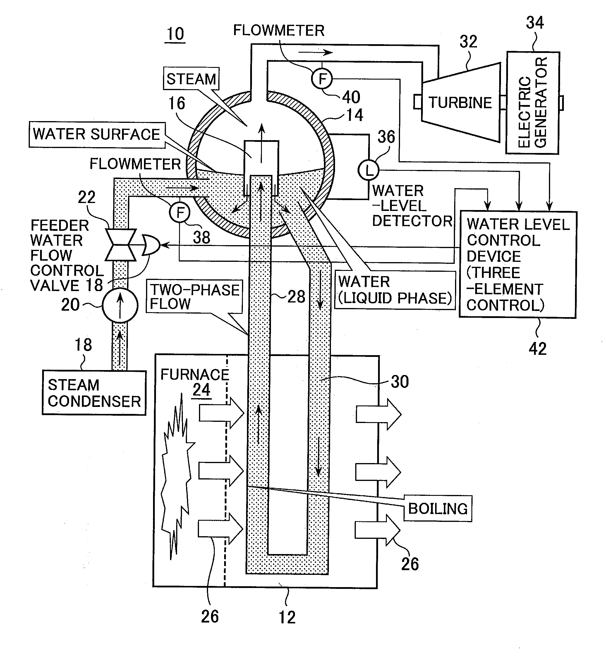
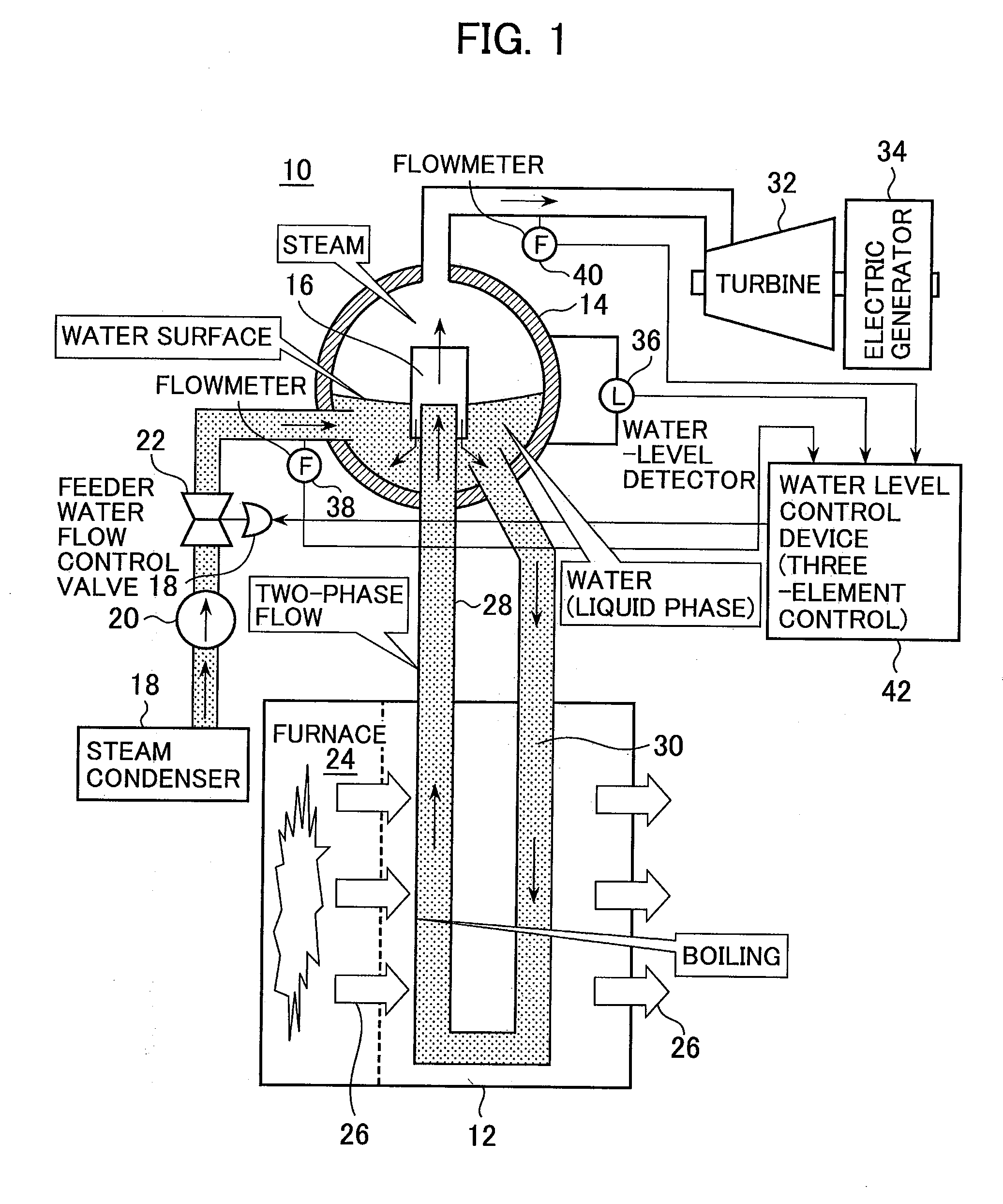
[0058]FIG. 6 is a diagram illustrating the configuration of a characteristic portion of the water level control system 10 according to a first embodiment of the present invention. In the first embodiment, the inlet of the swirl steam-water separator 16 is provided with a flowmeter 44 for measuring the flow rate of two-phase fluid, whereas a water outlet is provided with a flowmeter 46. Flow rate signals measured by the flowmeters 44 and 46 are entered into the water level control section 42. The present embodiment determines the change rate of the volume of water retained in the steam-water separator 16 in accordance with the difference between the flow rate of liquid flowing from the boiler 12 to the steam-water separator 16 and the flow rate of liquid flowing from the steam-water separator 16 to the liquid-phase section of the steam drum 14 plus the flow rate of steam supplied to the turbine 32.
[0059]The water level control section 42 determines the deviation signal (S1) that indi...
second embodiment
[0064]FIG. 7 is a diagram illustrating the configuration of a characteristic portion of the water level control system 10 according to a second embodiment of the present invention. The second embodiment includes a water-level detector 48 for detecting the water level of water retained in the steam-water separator 16. A water level signal measured by the water-level detector 48 enters the water level control section 42. The present embodiment determines the volume of water to be retained in the steam-water separator 16 in accordance with the water level in the steam-water separator 16, and then determines the change rate of the volume of water to be retained in the steam-water separator 16 in accordance with the determined volume of the water.
[0065]The water level control section 42 determines the deviation signal (S1) that indicates the deviation between the target water level (water level setpoint) in the steam drum 14 and the water level detected by the water-level detector 36. Me...
third embodiment
[0068]FIG. 8 is a diagram illustrating the configuration of a characteristic portion of the water level control system 10 according to a third embodiment of the present invention. The third embodiment determines the volume of water to be retained in the steam-water separator 16 in accordance with the flow rate of steam supplied from the steam drum 14 to the turbine32, which is detected by the flowmeter 40, and then determines the change rate of the volume of water to be retained in the steam-water separator 16 in accordance with the determined volume of the water.
[0069]The water level control section 42 determines the deviation signal (S1) that indicates the deviation between the target water level (water level setpoint) in the steam drum 14 and the water level detected by the water-level detector 36. Meanwhile, the water level control section 42 determines the volume of retained water in the steam-water separator 16 from a detected steam flow rate signal (S30) by using the function...
PUM
 Abstract
Description
Claims
Application Information
 - R&D
- Intellectual Property
- Life Sciences
- Materials
- Tech Scout
- Unparalleled Data Quality
- Higher Quality Content
- 60% Fewer Hallucinations
Browse by: Latest US Patents, China's latest patents, Technical Efficacy Thesaurus, Application Domain, Technology Topic, Popular Technical Reports.
© 2025 PatSnap. All rights reserved.Legal|Privacy policy|Modern Slavery Act Transparency Statement|Sitemap|About US| Contact US: help@patsnap.com


