Fault-tolerant chemical injection system for oil and gas wells

Active Publication Date: 2010-05-27
NAT COUPLING
View PDF9 Cites 33 Cited by
  • Summary
  • Abstract
  • Description
  • Claims
  • Application Information

AI Technical Summary

Benefits of technology

[0014]In a metering body according to the present invention, the free piston is provided with two, mechanically-actuated valves which may be poppet valves. When open, the poppet valves permit fluid to flow from one side of the free piston to the other—i.e., fluid may flow from one chamber of the displacement cylinder to the other chamber. During normal operation of the metering body, the valves remain closed. However, if a fault occurs in the system which prevents the flow of fluid in the metering body to reverse at the end of the piston's stroke, at least one of the valves will open when the free piston comes within a preselected distance from a mechanical stop. In one particular preferred embodiment, the interior face of a cylinder head comprises the mechanical stop. With the valve open, pressurized fluid can continue to flow through the metering body at the last selected flow rate. In this way, a fault-tolerant system may be provided.

Problems solved by technology

However, if a fault occurs in the system which prevents the flow of fluid in the metering body to reverse at the end of the piston's stroke, at least one of the valves will open when the free piston comes within a preselected distance from a mechanical stop.

Method used


Image

  • Fault-tolerant chemical injection system for oil and gas wells
  • Fault-tolerant chemical injection system for oil and gas wells
  • Fault-tolerant chemical injection system for oil and gas wells

Examples


Embodiment Construction

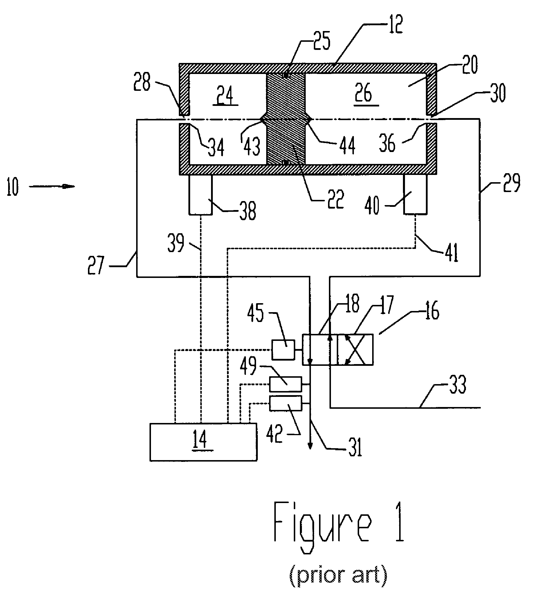
[0022]FIG. 1 schematically illustrates details of a metering body 12 interconnected with a control system 14 and a multi-position valve 16 in a chemical injection system 10. The metering body 12 has a bore 20 for containing chemical fluid to be delivered to a well. An axially movable free piston 22 in bore 20 divides metering body 12 into variable-volume first and second chambers 24, 26. Free piston 22 seals with metering body 12 with a sealing member such as O-ring 25. Metering body 12 and free piston 22 conventionally comprise a cylinder and piston assembly, as shown. First and second input-output ports 28, 30 are provided for passing fluid into and out of first and second chambers 24, 26. Supply line 33 supplies chemical fluids at high pressure through multi-position valve 16 to metering body 12.

[0023]In a first valve position shown in FIG. 1, illustrated conceptually by alignment of parallel line segments 18 with lines 31 and 33, fluid passes from supply line 33, through multi-p...


PUM


Abstract

A metering body for a chemical injection system comprises a free piston having a pair of mechanically-actuated poppet valves which may individually open to permit fluid to pass from one side of the free piston to the other. The free piston slides within a cylinder having cylinder heads at opposing ends. Input / output ports are provided in the cylinder heads. In a preferred embodiment, the poppet valves have actuators that extend beyond the opposing faces of the free piston. If one face of the piston moves to within a predetermined distance of a cylinder head, the actuator contacts the cylinder head and further movement of the piston causes the corresponding poppet valve to open, permitting fluid to flow through the piston. In this way, a fault-tolerant system may be implemented. If a power interruption or other failure of the controller occurs, the system will continue to supply fluid at the most recently selected flow rate. When power is restored (or the fault is corrected), the controller causes a valve to reverse the flow of fluid through the metering body and the spring-loaded poppet valve will close as the free piston moves away from the cylinder head.

Description

CROSS-REFERENCE TO RELATED APPLICATIONS [0001]NoneSTATEMENT REGARDING FEDERALLY SPONSORED RESEARCH OR DEVELOPMENT[0002]NoneBACKGROUND OF THE INVENTION[0003]1. Field of the Invention[0004]This invention relates to chemical injection systems for oil and gas wells. More particularly, it relates to a positive-displacement volumetric device for use in systems for injecting liquid-phase chemical treatment agents into undersea wells.[0005]2. Description of the Related Art Including Information Disclosed Under 37 CFR 1.97 and 1.98[0006]A variety of chemical agents are injected into hydrocarbon wells for the control of corrosion, hydrates, asphaltenes, paraffins, scale and the like. These chemical agents are typically in the liquid phase and are pumped into the well at a selected rate using a chemical injection system. For undersea wells, the chemical supply and pump may be located on a production platform and are most commonly connected to the wellhead via an umbilical line. If metering of ...

Claims


Application Information

Patent Timeline
Patent Type & Authority Applications(United States)
IPC IPC(8): F16K31/36G01F11/04F16K31/06
CPCG01F11/04E21B33/068E21B34/101Y10T137/7759Y10T137/7761Y10T137/794
Inventor WATSON, RICHARD R.
Owner NAT COUPLING
Why Eureka
Try Eureka