Heating and hot water supply apparatus

a technology of hot water supply and heater, which is applied in the direction of domestic hot water supply system, heating types, applications, etc., can solve the problems of insufficient heating in regions, inability to efficiently supply hot water in hot water tanks, and worse heat derivation efficiency

Inactive Publication Date: 2010-05-27
DAIKIN IND LTD
View PDF28 Cites 20 Cited by
  • Summary
  • Abstract
  • Description
  • Claims
  • Application Information

AI Technical Summary

Benefits of technology

[0026]According to the heating and hot water supply apparatus of the invention, hot water stored in the hot water tank is fed to the heating terminal through the circulation path so that heat of the hot water is supplied to the heating terminal efficiently without passing through the heat exchanger. Thus, the heating and hot water supply apparatus is enabled to fulfill enough heating in such regions of high heating loads as Nordic countries where 24-hour heating operation is involved in winter.

Problems solved by technology

As a result, efficiency of heat derivation is worsened.
This means that heat of the hot water in the hot water tank cannot be efficiently supplied to the heater.
Therefore, the conventional heating and hot water supply apparatus described above has a problem that with 24-hour heating operation in winter, enough heating cannot be fulfilled in regions, such as Nordic countries, which have high heating loads involving a heating load to hot water supply load ratio of 10:1.

Method used


Image

  • Heating and hot water supply apparatus
  • Heating and hot water supply apparatus
  • Heating and hot water supply apparatus

Examples


first embodiment

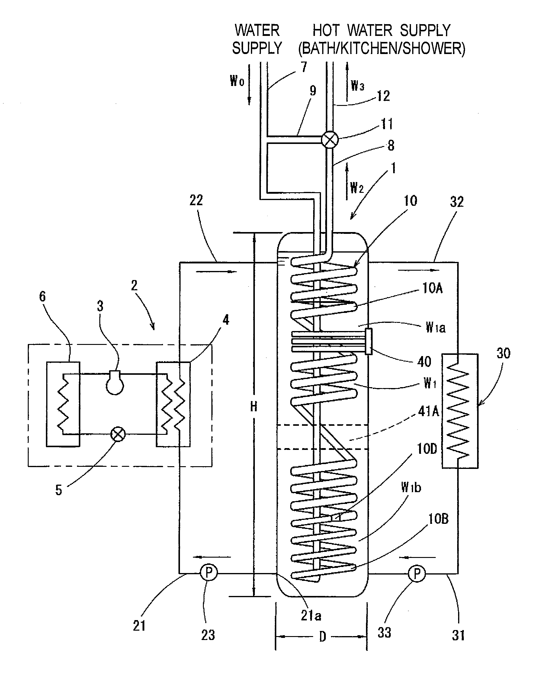
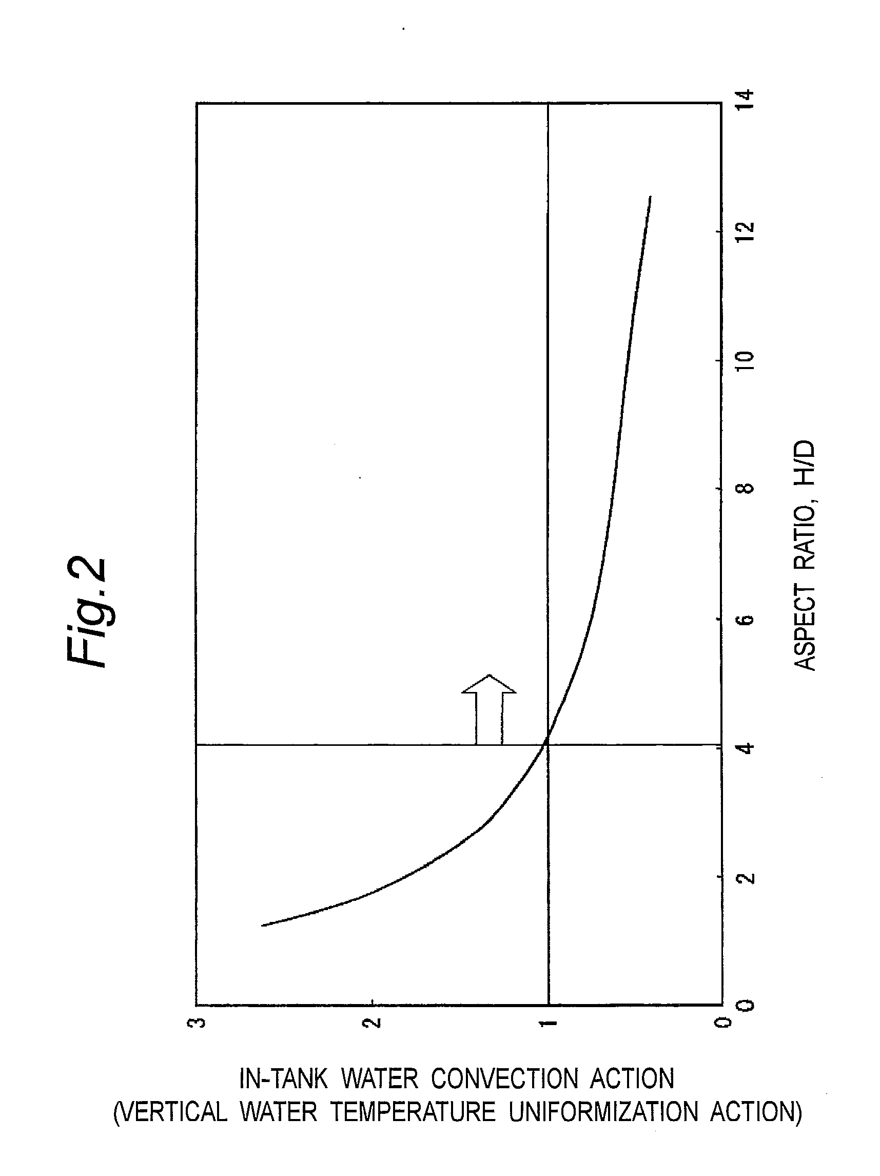
[0034]More specifically, the heating and hot water supply apparatus according to the invention, as illustrated in FIG. 1, includes: a heat pump unit 2 having a compressor 3 for compressing a refrigerant, a radiative heat exchanger 4 for condensing the compressed refrigerant to radiate heat, and an endothermic heat exchanger 6 for evaporating the condensed refrigerant and absorbing heat from the air; and a water storage tank 1 which is connected to the heat pump unit 2 via a lower-position side water pipe 21 and a higher-position side water pipe 22 and in which stored water W1, i.e. hot water heated by the radiative heat exchanger 4 is stored and moreover which is internally provided with an in-tank heat exchanger 10 for performing heat exchange with the stored water W1 to heat flow-through water W2, i.e. supply hot water flowing through the interior of the in-tank heat exchanger 10, wherein the water storage tank aspect ratio (H / D), i.e., a ratio of the inner height H to the inner d...

second embodiment

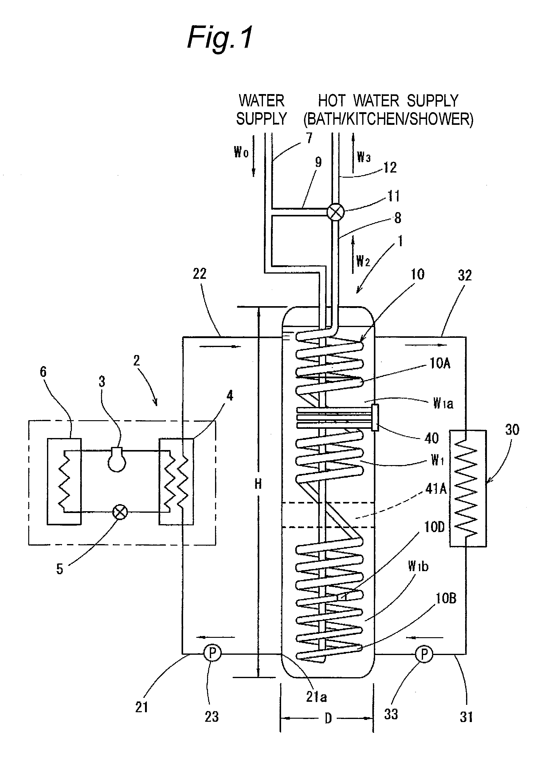
[0042]Next, with regard to a heating and hot water supply apparatus of a second embodiment, FIG. 3 shows another example of the actualization for facilitating the vertical temperature difference creating action for the stored water W1 in the water storage tank 1 by the in-tank heat exchanger 10. The heating and hot water supply apparatus shown in FIG. 3 is similar to the heating and hot water supply apparatus shown in FIG. 1 in that the water-supply side pipe line 7 running to the in-tank heat exchanger 10 is vertically provided in a straight pipe shape up to a vicinity of the bottom portion within the water storage tank 1 while the range from the lower end of the water-supply side pipe line 7 to the outlet-side pipe line 8 on the exit side is provided by the in-tank heat exchanger 10, which is a coiled tubular member. However, in the heating and hot water supply apparatus shown in FIG. 3, the in-tank heat exchanger 10, which is formed as a coiled tubular member, is made higher in c...


PUM


Abstract

A heating and hot water supply apparatus is provided with a heat pump unit (2), a water storage tank (1), a heat exchanger (10) in the water tank and pipe lines (31, 32). Hot water stored in the water storage tank (1) by being guided by the pipe line (32) passes through a radiator (30) outside the water storage tank (1), then returns into the storage tank (1) by being guided by the pipe line (31) for circulation. Thus, the radiator (30) can directly use heat of large quantity hot water stored in the water storage tank (1).

Description

TECHNICAL FIELD[0001]The present invention relates to a heating and hot water supply apparatus to be used for heating and hot water supply.BACKGROUND ART[0002]Conventionally, there is provided a heating and hot water supply apparatus as disclosed in JP 2004-232914 A. This heating and hot water supply apparatus includes a heat pump, a hot water tank for storing hot water heated by the heat pump, a heat exchanger placed only in an upper region within the hot water tank, and a heater connected to the heat exchanger.[0003]The hot water tank is connected to a faucet via a hot water outlet pipe. Opening the faucet allows hot water stored in the hot water tank to be taken out from the faucet.[0004]The heater performs heating operation by using the hot water stored in the hot water tank. More specifically, when the heating operation is started, a heating medium in the heat exchanger is heated by the hot water contained in the hot water tank. The heated heating medium is fed to the heater to...

Claims


Application Information

Patent Timeline
Patent Type & Authority Applications(United States)
IPC IPC(8): F28D7/00F28F13/12F25B13/00
CPCF24D11/0228F24D17/02Y02E60/142Y02B30/126Y02B10/70F28D2020/0086F28D2020/0078F28D20/0039F28D7/028F28D7/024F24D2220/06F24D2200/08F24D2200/12F24D2240/10F24D2220/08F24D2220/2009F24D2220/209F24D11/0214Y02E60/14
Inventor FURUI, SYUUJINUMATA, MITSUHARU
Owner DAIKIN IND LTD
Why Eureka
Try Eureka