Shield conductor

a shield conductor and shield technology, applied in the direction of insulated conductors, power cables, cables, etc., can solve the problems of affecting the heat radiation to the outside, the heat dissipation property of the shield conductor in the part using the sleeve pipe can be improved, and the radiation performance of the heat radiation from the wires is a problem, so as to achieve convenient connection, improve the heat dissipation property of the shield conductor in the part using th

Inactive Publication Date: 2010-05-27
AUTONETWORKS TECH LTD +2
View PDF10 Cites 63 Cited by
  • Summary
  • Abstract
  • Description
  • Claims
  • Application Information

AI Technical Summary

Benefits of technology

[0011]According to the present invention, using the connecting member allows the sleeve pipe provided with the housing members arranged in a row for housing the wires and the corrugated tube to be easily connected. This enables the wires and the shielding layer housed inside of the sleeve pipe to be arranged in a relatively large space, wh

Problems solved by technology

However, in the above configuration where the wires are enwrapped by the corrugated tube, the radiation performance of the heat radiation from the wires is a problem.
The heat conductivity of the air is relatively low, and this air layer therefore disturbs the heat radiation to the outside.
As a result, the heat generated from the wires re

Method used


Image

  • Shield conductor
  • Shield conductor
  • Shield conductor

Examples


Embodiment Construction

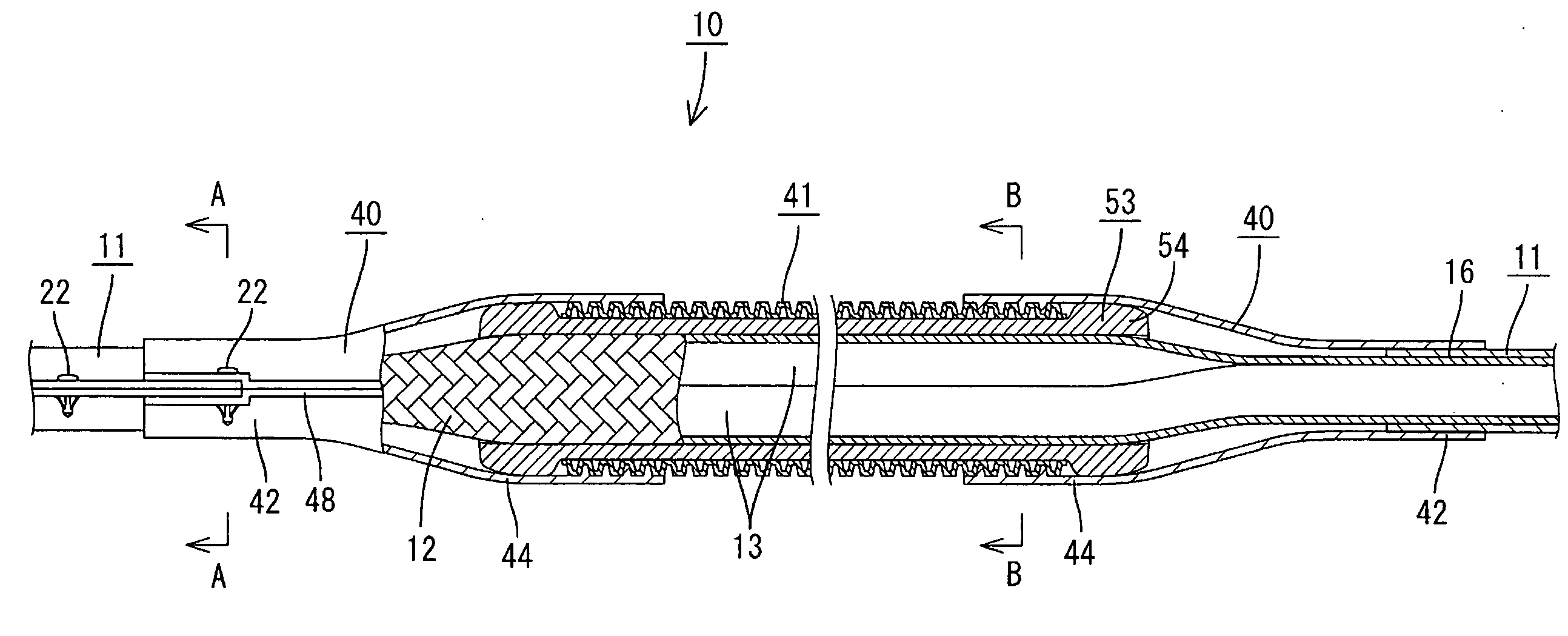
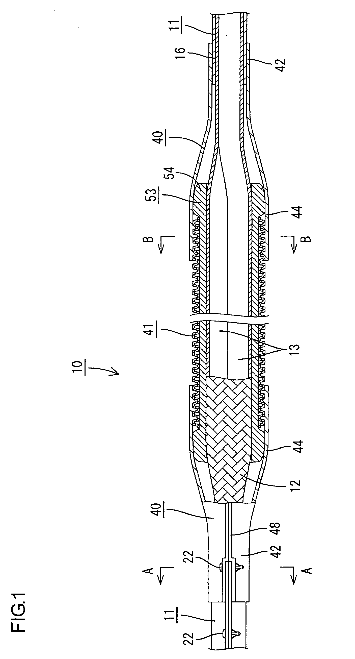
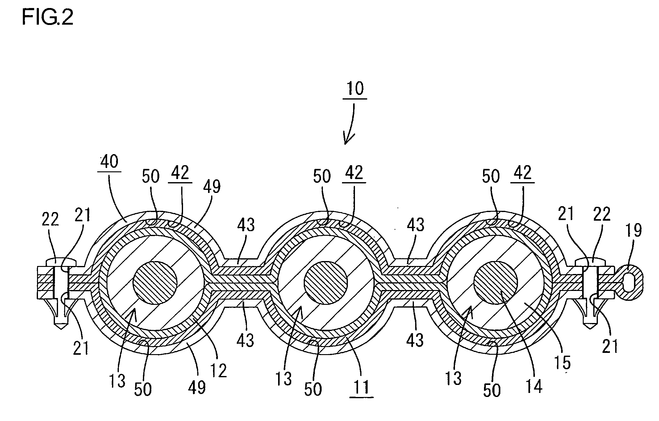
[0048]In reference to FIGS. 1 to 20, one embodiment in which the present invention is applied to a shield conductor 10 is described. The present embodiment is mounted in, for example, a vehicle (not shown) such as an electric vehicle and a hybrid vehicle, and electrically connects between equipments such as a battery (not shown), an inverter device (not shown), and a motor (not shown). The shield conductor 10 is fitted to the vehicle by a holding member (not shown) such as, for example, a clamp. As shown in FIG. 1, the shield conductor 10 according to the present embodiment is constituted by enwrapping the outer circumference of multiple (three in the present embodiment) of wires 13 by a braided wire 12 (corresponding to a shielding layer), and housing the wires 13 enwrapped by the braided wire 12 inside of the sleeve pipe 11, connecting member 40, and the corrugated tube 41.

[0049](Wire)

[0050]As shown in FIG. 4, the wire 13 is constituted by enwrapping the outer circumference of a c...


PUM


Abstract

This invention provides a shield conductor having heat dissipation property and flexibility. The shield conductor comprises: multiple wires; a shielding layer enwrapping the outer circumference of the wires while having flexibility; a sleeve pipe having multiple first housing members that are arranged in a row in a direction orthogonal to the axial direction of the wires and separately house the wires enwrapped by the shielding layer; a connecting member having multiple second housing members that are connected with each first housing member in the sleeve pipe and separately house the wires enwrapped by the shielding layer, while having a third housing member that is communicated with each second housing member and collectively houses the wires enwrapped by the shielding layer, and a corrugated tube connected with the third housing member in the connecting member and collectively housing the wires enwrapped by the shielding layer.

Description

TECHNICAL FIELD[0001]The present invention relates to a shield conductor.[0002]Conventionally, a shield conductor disclosed in Patent Literature 1 which is mounted in an electric vehicle and electrically connects between equipments such as an inverter and a motor has been well-known. This shield conductor comprises multiple wires, a braided wire enwrapping the wires, and a corrugated tube enwrapping the wires and the braided wire. With the above configuration, the shield conductor can obtain flexibility in its entirety. And as a result, the shield conductor can be bent at a relatively small radius of curvature, and thereby being easily arranged even in a relatively narrow space such as an engine room.[0003][Patent literature 1]: Japanese Unexamined Patent Publication No. 2004-172476DISCLOSURE OF THE INVENTION[0004]However, in the above configuration where the wires are enwrapped by the corrugated tube, the radiation performance of the heat radiation from the wires is a problem. In s...

Claims


Application Information

Patent Timeline
IPC IPC(8): H01B9/02
CPCH05K9/0098H01B7/426
Inventor WATANABE, KUNIHIKO
Owner AUTONETWORKS TECH LTD
Why Eureka
Try Eureka