
Vibration motor for portable terminal

a portable terminal and vibration motor technology, applied in the field of portable terminals, can solve the problems of users' inconvenience, difficulty in haptically recognizing whether, and limitations of conventional coin-type or bar-type vibration motors, etc., and achieve the effects of convenient control, improved vibration feeling, and rapid degradation of vibration for

Inactive Publication Date: 2010-05-27
SAMSUNG ELECTRONICS CO LTD
View PDF7 Cites 28 Cited by
  • Summary
  • Abstract
  • Description
  • Claims
  • Application Information

AI Technical Summary

Benefits of technology

[0012]Accordingly, the present invention has been made to solve the above-mentioned problems occurring in conventional devices, and the present invention provides a vibration motor for a portable terminal capable of providing a reliable haptic feedback function even during fast input via a touch screen.
[0013]Also, the present invention provides a vibration motor for a portable terminal which is easily controllable and generates a sufficient vibration force while manipulating a touch screen as it is operated over a broader frequency band.
[0014]Further, the present invention provides a vibration motor for a portable terminal which helps users easily recognize key inputs on a touch screen when realizing a haptic feedback function as it has a high resonant frequency.
[0019]A vibration motor of a portable terminal according to the present invention as described above vibrates with a higher frequency than a conventional vibration motor. Therefore, the vibration motor according to the present invention can provide better vibration feeling to users for providing a haptic feedback function during touch screen operation.
[0020]Further, the conventional vibration motor has a narrow operation frequency band range (150 to 200 Hz), which causes rapid degradation of vibration force when it goes out of the corresponding frequency band range. However, a vibration motor in accordance with the present invention operates in a frequency band range of 250 to 450 Hz, which makes it easy to control the inventive vibration motor for a haptic feedback function.
[0021]Moreover, conventional vibration motors require 50 to 90 ms to reach 50 percent of the maximum vibration force during initial operation. However, the vibration motor according to the present invention requires only 10 ms for the same operation. In addition, it takes 40 to 80 ms for conventional coin-type or bar-type vibration motors to reach a level of less than 50 percent of the maximum vibration force at the end of its operation. However, a vibration motor of the present invention requires only 50 ms to attain a level less than 10 percent of the maximum vibration force at the end of its operation. Therefore, use of the vibration motor according to the present invention can reduce the sense of an after-vibration during the touch screen operation, which is advantageous in realizing the haptic feedback function.

Problems solved by technology

On the other hand, since the keypad employed in the touch screen cannot provide the same sense of clicking as that of the dome switch, users have to directly check the value to be input through a display device.
Hence, much effort has been placed on removing the users' inconvenience to check the input value through the display device by providing a haptic feedback function to the portable terminal which employs an input device adopting a touch screen method.
Conventional coin type or bar type vibration motors, however, have a limitation in performing the haptic feedback function because of their long response time.
Therefore, users have difficulties in haptically recognizing whether the signal value of the selected key is correctly input while making continuous key inputs at high speeds.
But such a conventional linear motor has drawbacks in that it has only one value of resonant frequency.
However, such a resonant frequency range reveals limitations in providing the haptic feedback function to acknowledge users' manipulations on the touch screen.

Method used


Image

  • Vibration motor for portable terminal
  • Vibration motor for portable terminal
  • Vibration motor for portable terminal

Examples


Embodiment Construction

[0029]Hereinafter, exemplary embodiments of the present invention will be described with reference to the accompanying drawings. In the following description, a detailed description of known functions and configurations incorporated herein will be omitted when it may make the subject matter of the present invention rather unclear.

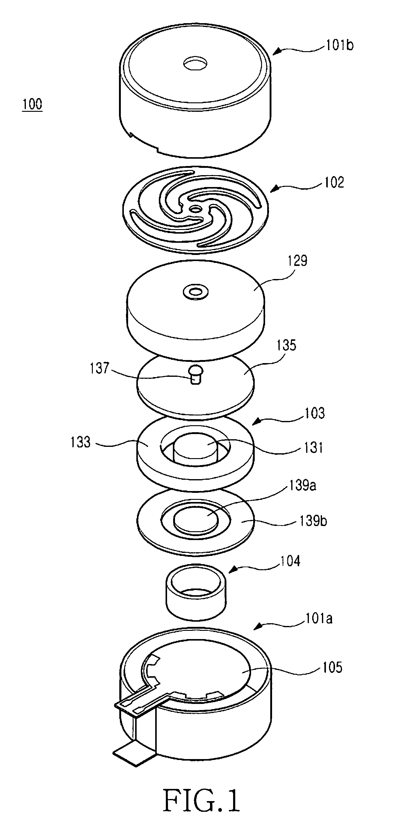
[0030]The present invention discloses a vibration motor for a portable terminal, wherein a coil is disposed between a pair of magnetic substances which are concentrically arranged to each other, and the magnetic substances are supported through an elastic body, so that the vibration motor can be vibrated by both an electromagnetic force generated between the magnetic substances and the coil and by an elastic force of the elastic body. In this regard, a weight can be used to adjust the resonant frequency thereof, and the magnetic substances can be coupled to the elastic body using the weight.

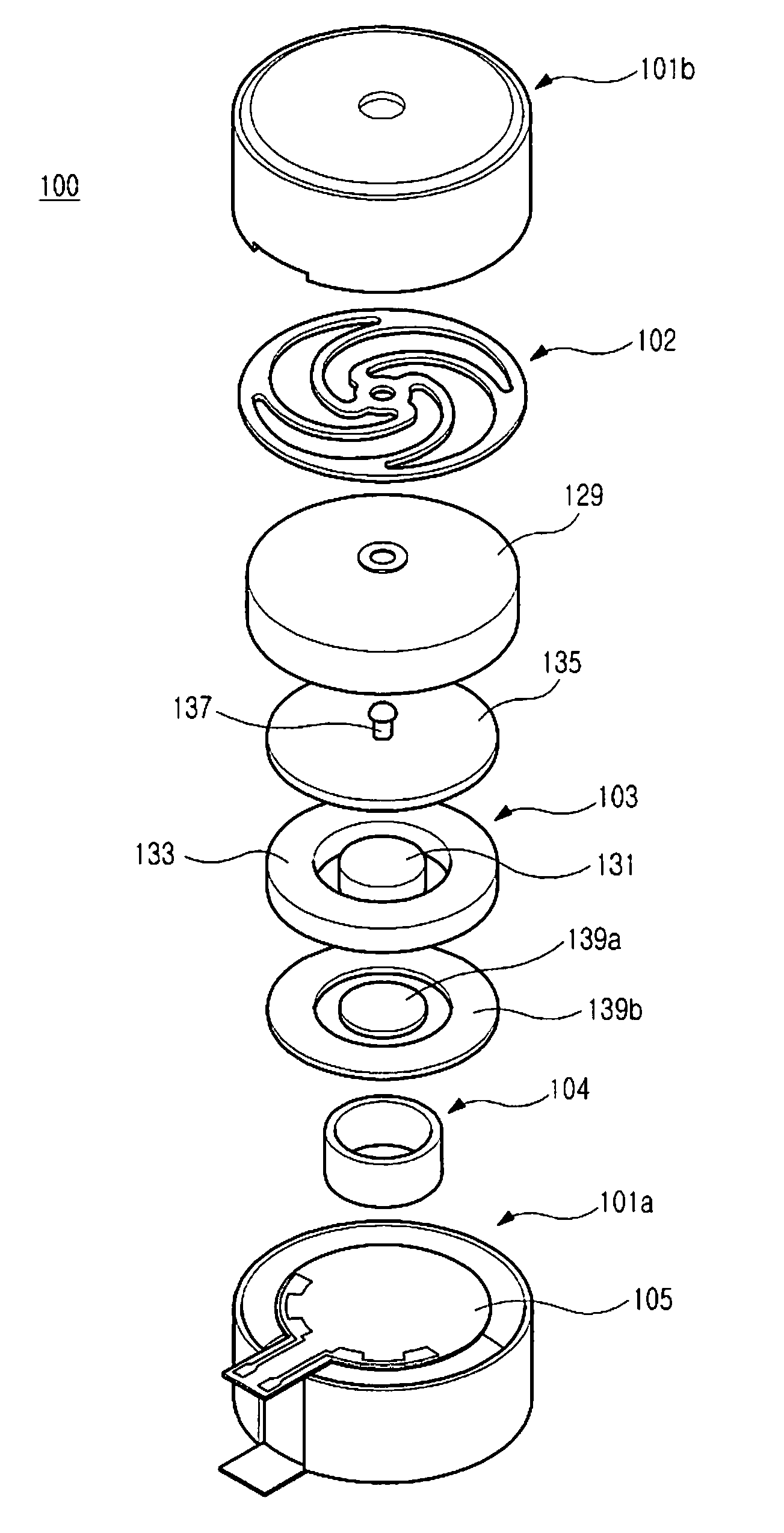
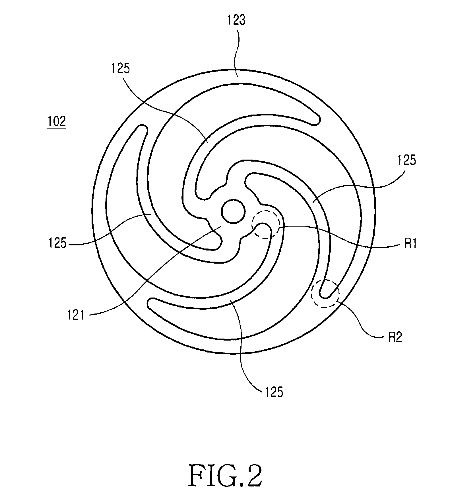
[0031]Referring now to FIGS. 1 through 4, a vibration motor 100 for...


PUM


Abstract

Disclosed is a vibration motor for a portable terminal, including a flat spring; a cylindrical magnetic substance mounted on the flat spring; an annular magnetic substance disposed around the cylindrical magnetic substance mounted on the flat spring; and a coil disposed between the cylindrical magnetic substance and the annular magnetic substance, wherein the magnetic substances perform a linear reciprocal movement by the electromagnetic force generated between the magnetic substances and the coil and by the elastic force of the flat spring as an electric current is applied to the coil. The vibration motor operates at higher resonant frequencies than those of conventional vibration motors, thereby improving the sense of an after-vibration and realizing a delicate haptic feedback function.

Description

PRIORITY[0001]This application claims the priority under 35 U.S.C. §119(a) to an application filed in the Korean Industrial Property Office on Nov. 24, 2008 and assigned Serial No. 10-2008-0117101, the contents of which are incorporated herein by reference.BACKGROUND OF THE INVENTION[0002]1. Field of the Invention[0003]The present invention relates to a portable terminal, and, more particularly, to a vibration motor for a portable terminal capable of providing a haptic feedback function.[0004]2. Description of the Related Art[0005]In general, the term haptic feedback includes a driving force feedback function, such as the type used for remote control of a robot arm, and refers to a method of information feedback based on the sense of touch or user skin contact. Recently, efforts have been made to utilize haptic feedback as a vibration function to inform users of when a call is received as well as a notice function to confirm the correct signal input of a selected key when manipulati...

Claims


Application Information

Patent Timeline
Patent Type & Authority Applications(United States)
IPC IPC(8): H02K33/00
CPCH02K33/16B06B1/045H02K33/02H02K7/065
Inventor YUN, IN-KUKLEE, EUN-HWAKIM, INBAE, YU-DONG
Owner SAMSUNG ELECTRONICS CO LTD
Learn More