Cooled gas turbine vane assembly

a technology of gas turbine engine and cooling vane, which is applied in the direction of machines/engines, liquid fuel engines, other chemical processes, etc., can solve the problems of excessive operating temperature often exceed the material capability of blades and vanes, so as to reduce the stiffness of the inner diameter platform and increase the thermal deflection

Active Publication Date: 2010-05-27
H2 IP UK LTD
View PDF7 Cites 112 Cited by
  • Summary
  • Abstract
  • Description
  • Claims
  • Application Information

AI Technical Summary

Benefits of technology

[0007]In yet another embodiment, an inner diameter platform of a gas turbine vane capable of increased thermal deflection comprise a gas path surface separated from a cold surface by a platform thickness, a forward pan, and an aft cover fixed to the cold surface. The platform thickness having an undercut extending between the gas path surface and cool surface, such that the undercut reduces stiffness of the inner diameter platform adjacent to the aft cover.

Problems solved by technology

These blades and vanes are subject to extremely high operating temperatures, often times upwards of 2800 deg. F. These temperatures often exceed the material capability from which the blades and vanes are made.
Extreme temps also cause thermal growth in the component, which if not permitted, causes thermal stresses and can lead to cracking.

Method used


Image

  • Cooled gas turbine vane assembly
  • Cooled gas turbine vane assembly
  • Cooled gas turbine vane assembly

Examples


Embodiment Construction

[0023]The subject matter of the present invention is described with specificity herein to meet statutory requirements. However, the description itself is not intended to limit the scope of this patent. Rather, the inventors have contemplated that the claimed subject matter might also be embodied in other ways, to include different components, combinations of components, steps, or combinations of steps similar to the ones described in this document, in conjunction with other present or future technologies.

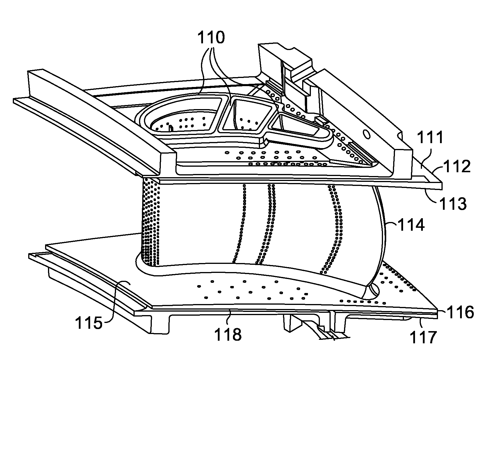
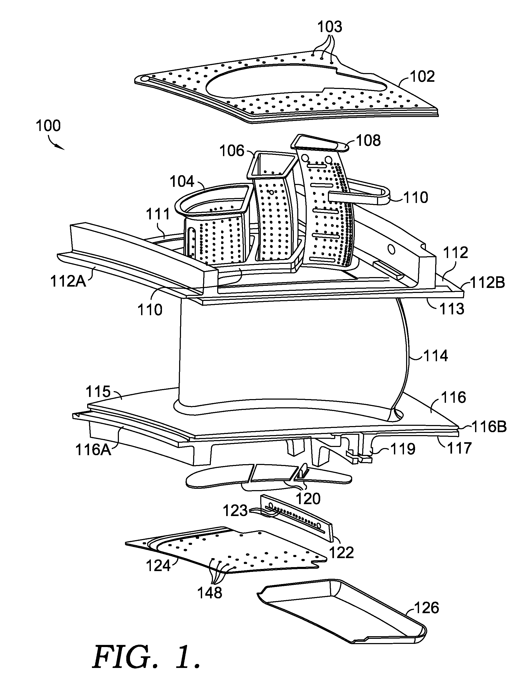
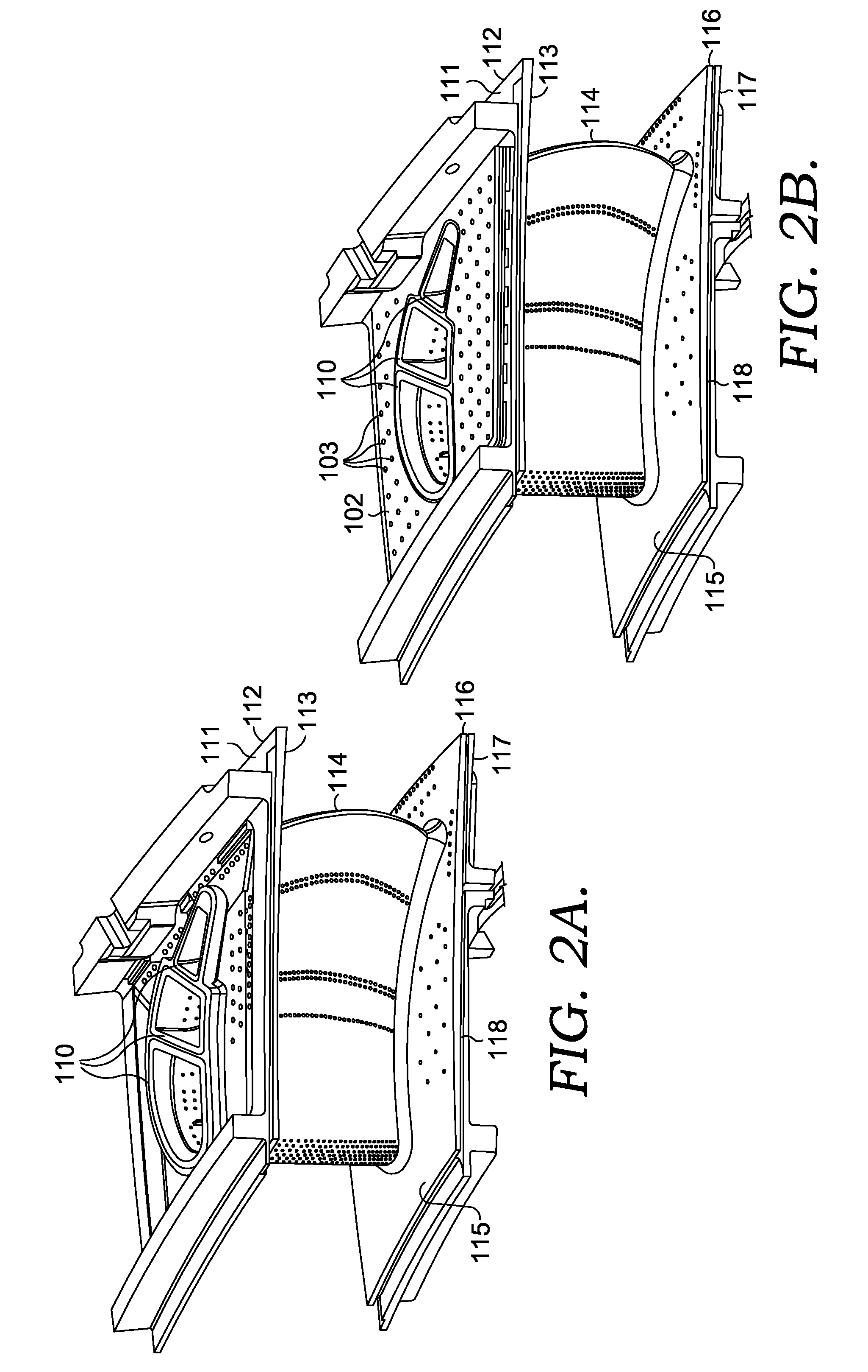
[0024]Referring to FIG. 1, an exploded view of the gas turbine vane 100, is depicted. An outer diameter pan 102 is affixed to the outer diameter platform 112 and has a plurality of holes 103. Acceptable means for fixing the outer diameter pan 102 to the outer diameter platform 112 includes welding or brazing. The outer diameter platform 112 has a cool surface 111 and a gas path surface 113. A plurality of cooling tubes 104, 106, and 108 extend from the outer diameter platform 112. S...


PUM


Abstract

A gas turbine vane to improve vane performance by addressing known failure mechanisms. A cooling circuit to the trailing edge of a vane airfoil is fed from the outer diameter platform, which prevents failure due to an oxidized and eroded airfoil trailing edge. The gas turbine includes an outer diameter platform, a hollow airfoil and an inner diameter platform with a plurality of cooling tubes extending radially through the airfoil. The cooling tubes are open at the outer diameter end and closed with covers at the inner diameter end. The inner diameter platform is also cooled and includes a meterplate for a portion of the cooling passageway and includes an undercut to improve thermal deflections of the inner diameter platform.

Description

TECHNICAL FIELD[0001]The present invention generally relates to a cooled vane component in a gas turbine engine. More specifically, the gas turbine vane has an improved cooling flow design and lower operating stresses.BACKGROUND OF THE INVENTION[0002]Gas turbine engines operate to produce mechanical work or thrust. Specifically, land-based gas turbine engines typically have a generator coupled thereto for the purposes of generating electricity. A gas turbine engine comprises an inlet that directs air to a compressor section, which has stages of rotating compressor blades. As the air passes through the compressor, the pressure of the air increases. The compressed air is then directed into one or more combustors where fuel is injected into the compressed air and the mixture is ignited. The hot combustion gases are then directed from the combustion section to a turbine section by a transition duct. The hot combustion gases cause the stages of the turbine to rotate, which in turn, cause...

Claims


Application Information

Patent Timeline
Patent Type & Authority Applications(United States)
IPC IPC(8): F02C7/12
CPCF01D5/188F01D9/041Y10S416/50F05D2260/202F05D2240/81F02C7/12F01D5/189
Inventor JOHNSTON, CHRISBASH, GARYTERIELE, TIMPARKER, DAVIDSTROHL, JAMES PAGE
Owner H2 IP UK LTD
Why Eureka
Try Eureka