Floating Pinion Bearing for a Reciprocating Pump

Active Publication Date: 2010-05-27
WEIR SPM
View PDF8 Cites 28 Cited by
  • Summary
  • Abstract
  • Description
  • Claims
  • Application Information

AI Technical Summary

Benefits of technology

[0007]One embodiment of a floating pinion bearing for a reciprocating pump assembly includes a power frame that houses a crankshaft. The crankshaft is mechanically connected to a large gear or bull gear on each end that is in mechanical engagement with a small gear or pinion. A bearing housing is integrally formed as part of the power frame with an increased width and a constant inner diameter. A pinion bearing assembly comprising an inner race, an outer race, and spherical bearings is placed around the shaft of the pinion. A sleeve with a flange area is placed around the shaft and is placed in flush contact with the inner and outer

Problems solved by technology

The installation process is t

Method used


Image

  • Floating Pinion Bearing for a Reciprocating Pump
  • Floating Pinion Bearing for a Reciprocating Pump
  • Floating Pinion Bearing for a Reciprocating Pump

Examples


Example

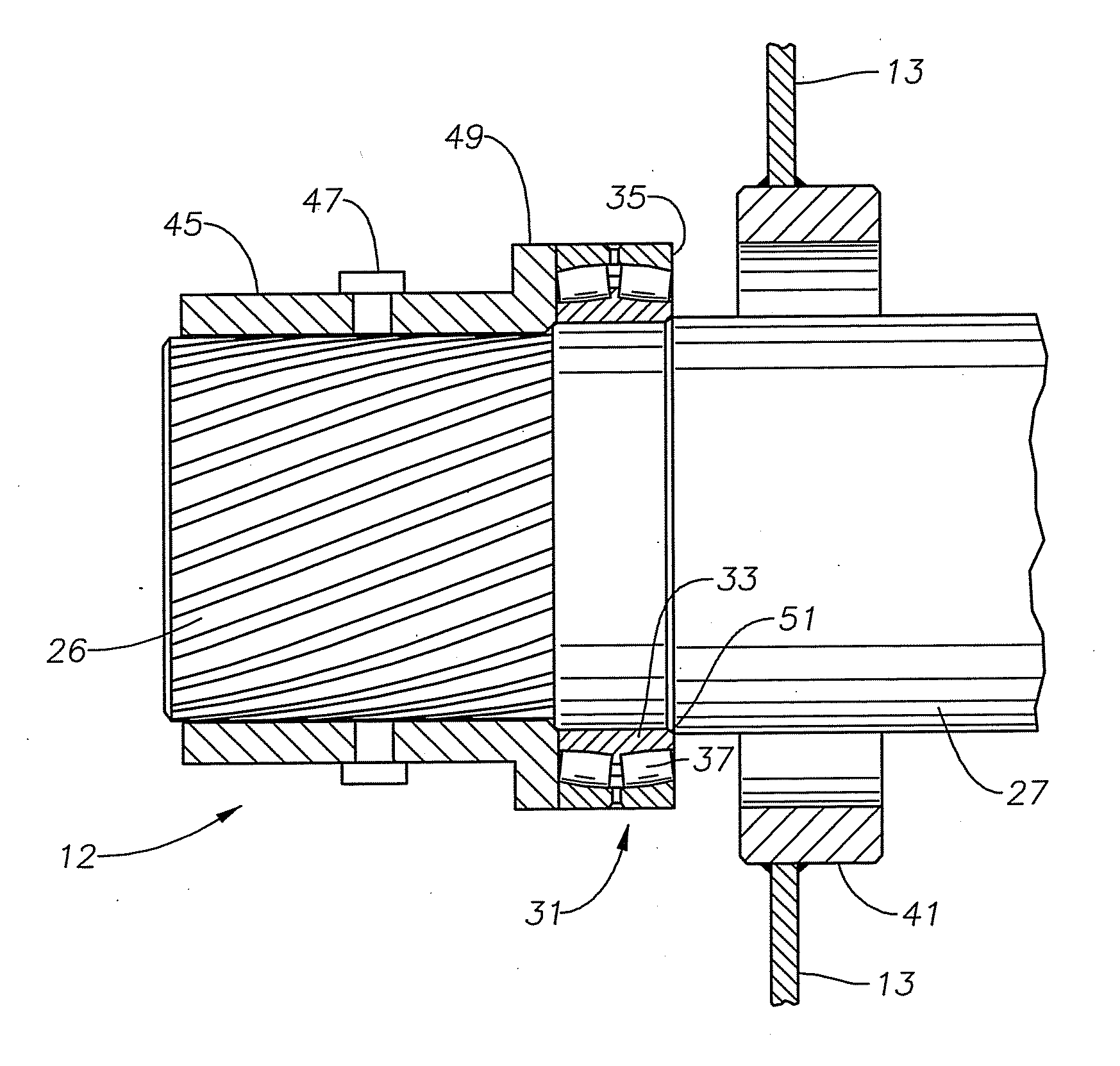
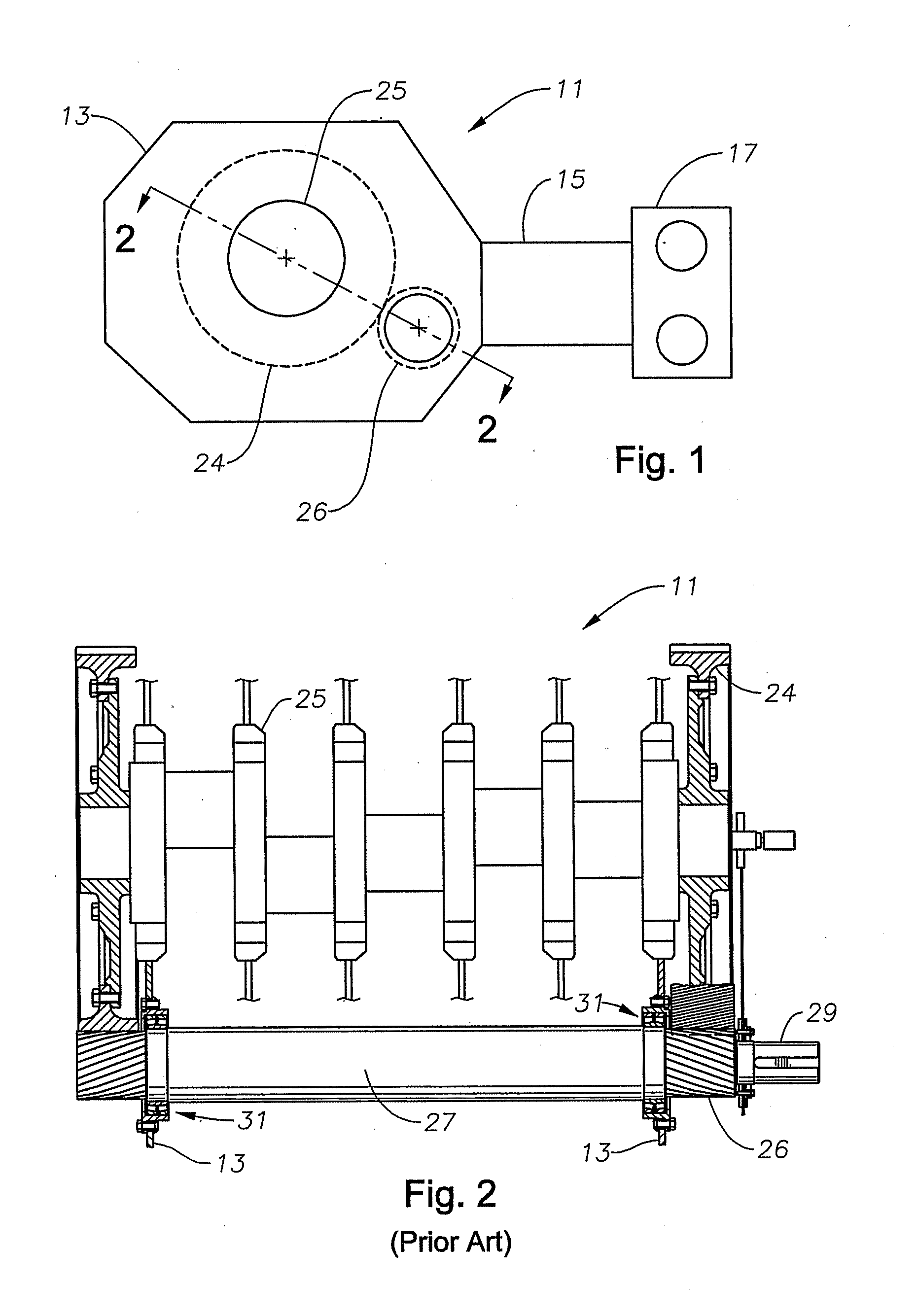
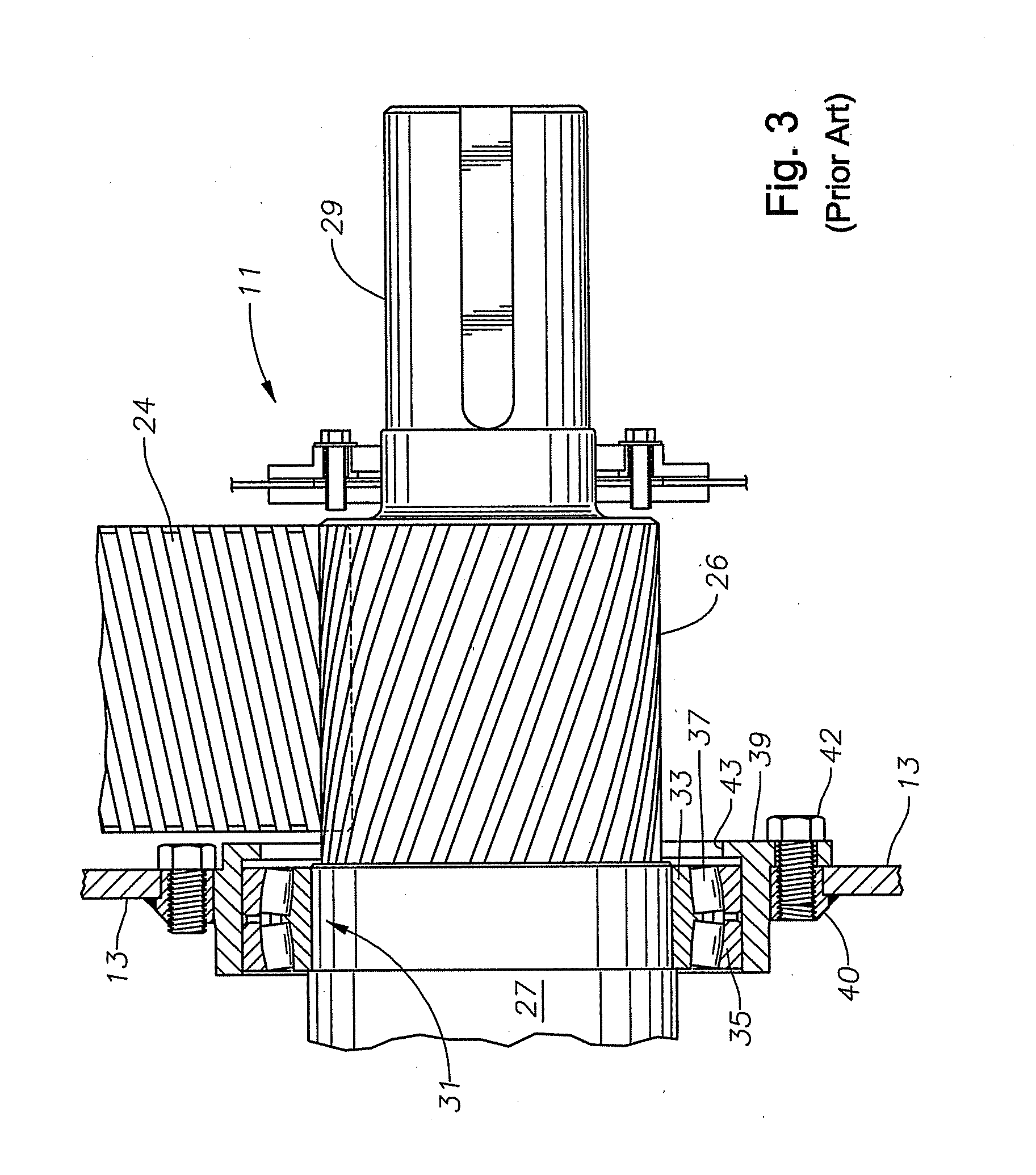
[0015]Pump 12 of this invention has the same general components as described in connection with FIGS. 1-3, including power frame housing 13, crankshaft 25, bull gears 24, and pinions 26 on each end of a pinion shaft 27. The pinion bearing assembly 31 is also the same, having an inner race 33, an outer race 35, and spherical bearings 37. Although referred to as “spherical,” bearings 37 are generally cylindrical, but with outward curved sides between its ends. Referring to FIG. 4, a bearing housing 41 is preferably formed separate from power frame housing 13 and securely fastened to power frame housing 13, as by welding. Bearing housing 41 is a cylindrical sleeve with a width greater than that of outer race 35 of pinion bearing assembly 31. The width of bearing housing 41 is also greater than the wall thickness of power frame housing 13 in this example. Inner race 33 is shrunk-fit onto pinion shaft 27.

[0016]An installation tool or sleeve 45 is used to install pinion 26 and pinion bear...


PUM

PropertyMeasurementUnit
Forceaaaaaaaaaa
Diameteraaaaaaaaaa
Widthaaaaaaaaaa

Abstract

A reciprocating pump assembly includes a power frame that houses a crankshaft. The crankshaft is mechanically connected to a large gear or bull gear on each end that is in mechanical engagement with a small gear or pinion bearing. A bearing housing is integrally formed as part of the power frame with an increased width and a constant inner diameter. A pinion bearing assembly, comprising an inner race, an outer race, and spherical bearings is placed around the shaft of the pinion bearing. The pinion is installed in the reciprocating pump assembly such that the bearing assembly rests on the bearing housing, which is integrally formed as part of the power frame. The bearing assembly is free to float in the bearing housing and provides for some lateral movement of the shaft and bearing assembly during operation of the reciprocating pump assembly.

Description

FIELD OF THE INVENTION[0001]The present invention relates in general to reciprocating pumps and, particular, to a floating pinion bearing for a reciprocating pump.BACKGROUND OF THE INVENTION[0002]In oil field operations, reciprocating pumps are often used for various purposes. Some reciprocating pumps, generally known as “service pumps,” are typically used for operations such as cementing, acidizing, or fracing a well. Typically, these service pumps run for relatively short periods of time, but they operate on a frequent basis. Often they are mounted to a truck or a skid for transport to various well sites. A pump might operate several times a week. In many applications, several pumps are connected in parallel to a single flow line.[0003]Referring to FIG. 1, a reciprocating pump assembly or pump 11 includes a crankshaft housing or power frame housing 13 that comprises a majority of the outer surface of reciprocating pump 12. A plunger or plunger rod housing 15 attaches to an end of ...

Claims


Application Information

Patent Timeline
IPC IPC(8): F04B9/04B23P11/00
CPCF04B9/02Y10T29/49236F04B9/04
Inventor PATEL, PANKAJ H.MATZNER, MARK D.
Owner WEIR SPM
Why Eureka
Try Eureka