Fluid pump assembly

Inactive Publication Date: 2010-05-27
DELPHI TECH HLDG S A R L
View PDF11 Cites 5 Cited by
  • Summary
  • Abstract
  • Description
  • Claims
  • Application Information

AI Technical Summary

Benefits of technology

[0013]The cam may be provided with a low friction coating, for example a soft phosphate or PTFE coating, which deforms, in use, to the profile of the radial bearing. The profile of the coating on the cam being matched with the profile of the radial bearing provides good conditions for promotio

Problems solved by technology

A fuel pump of radial pump design necessarily occupies a relatively high volume and, for some engine applications, this can be a disadvantage.
Furthermore, the tappets are prone to wear

Method used


Image

  • Fluid pump assembly
  • Fluid pump assembly
  • Fluid pump assembly

Examples


Example

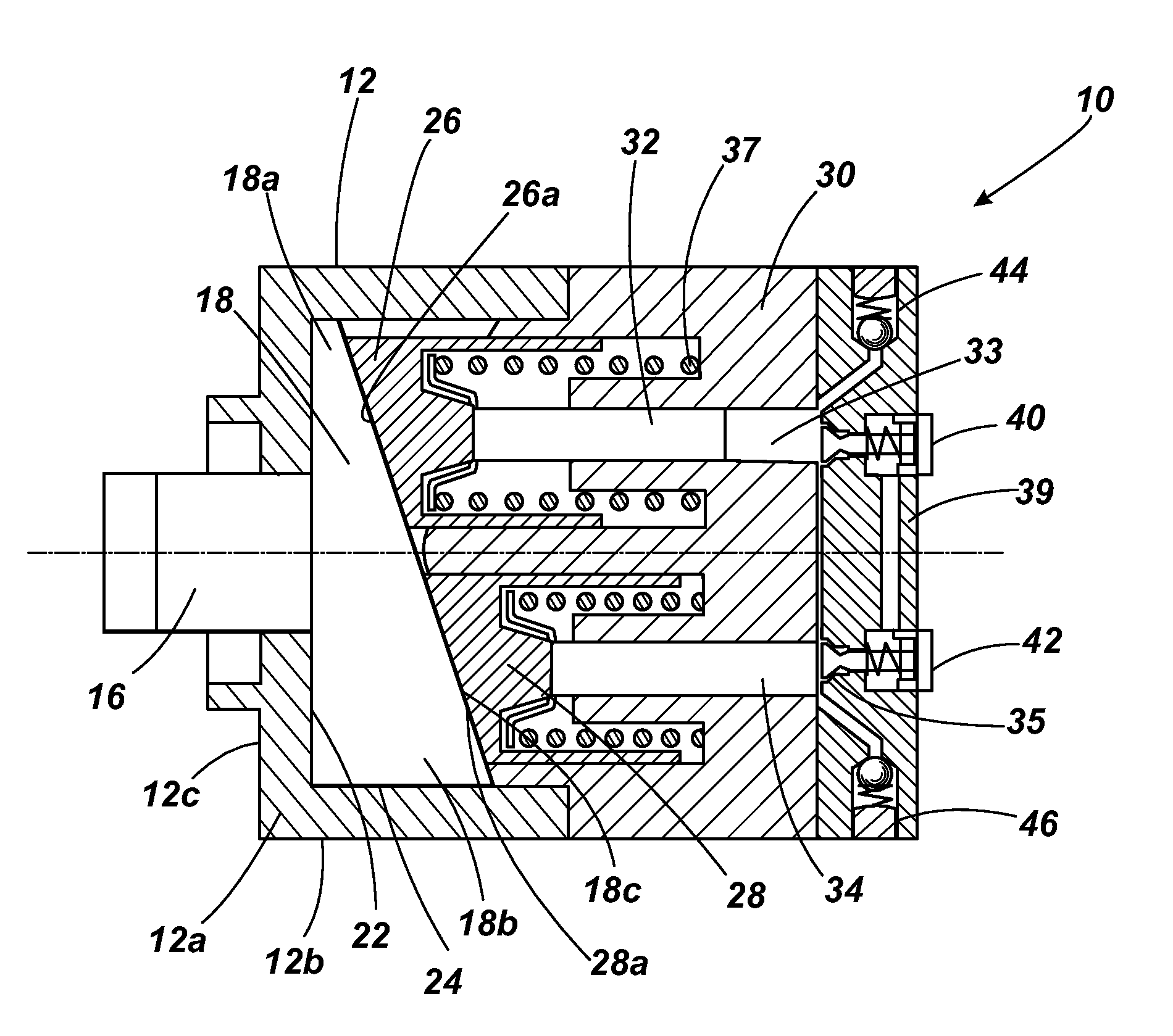
[0037]Referring to FIG. 1, a first embodiment of the fuel pump assembly 10 of the invention includes a pump housing having a first housing part 12 which is provided with a central bore for receiving a drive shaft 16 (only a part of which is shown). The first housing part includes a front plate 12a of the pump housing and a cylindrical body 12b towards the rear. The rear end of the drive shaft 16 carries a cam 18 which rotates with the drive shaft 16, in use. Typically, the front or input end of the drive shaft is driven by the engine through an Oldham coupling, as would be familiar to a person skilled in the art.

[0038]The cam 18 is wedge-shaped and so has a thin end 18a and a thick end 18b with a bevelled contact surface 18c on its front face. The back face of the cam 18 is planar and acts against an axially-facing internal surface of the pump housing 12, which therefore acts as an axial bearing 22 for the cam 18 as it rotates. The outer surface of the cam, at its thick end 18b, bea...


PUM


Abstract

A fluid pump assembly comprising a driven cam and a reciprocating member reciprocal within a bore provided in a pump housing as the cam is driven, in use, to cause pressurisation of fluid within a pump chamber. The pump assembly further comprises an interface between the cam and the reciprocating member, for example in the form of bevelled surfaces of the cam and the reciprocating member, which serve to drive the reciprocating member (i) to translate in a first, axial direction within the bore and (ii) to rotate within the bore in a second, rotational direction. An optional feature of the fluid pump assembly is that the pump housing defines a bearing for the cam which is provided with a recess to define a region of weakness to allow the bearing to deflect, in use, thereby to provide an increased lubrication volume between the cam and the bearing. The reciprocating member may take the form of a tappet which cooperates with a pumping plunger to pressurise fluid within the pump chamber.

Description

TECHNICAL FIELD[0001]The invention relates to a fluid pump assembly and, in particular, but not exclusively, to a pump assembly for fuel. The pump assembly is suitable for use in a common rail fuel injection system for supplying high pressure fuel to a compression ignition (diesel) internal combustion engine. In particular, the invention has application in a pump assembly of the type in which an engine driven cam imparts reciprocating, pumping motion to a drive member.BACKGROUND TO THE INVENTION[0002]One known common rail fuel pump is of radial pump design and includes three pumping plungers arranged at equi-angularly spaced locations around an engine driven cam—such a pump is described in, for example, WO 2004 / 104409. In this pump, each plunger is mounted within a plunger bore provided in a pump head mounted to a main pump housing. As the cam is driven in use, the plungers are caused to reciprocate within their bores in a phased, cyclical manner. As the plungers reciprocate, each c...

Claims


Application Information

Patent Timeline
IPC IPC(8): F04B9/04
CPCF02M59/102F04B1/0426F04B9/042F04B1/326F04B1/12
Inventor HOPLEY, DANIEL JEREMY
Owner DELPHI TECH HLDG S A R L
Why Eureka
Try Eureka